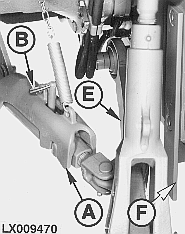
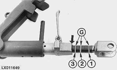
Adjusting Stabilizing Support (If Equipped)1. Back tractor to center of implement.2. Turn off engine and remove key. 3. Remove ring (B) and raise channel (A). 4. Turn adjuster rod using lever (H) to align groove 2 or 3 with edge (see arrow). See following table for groove-to-hitch category.
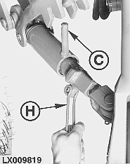
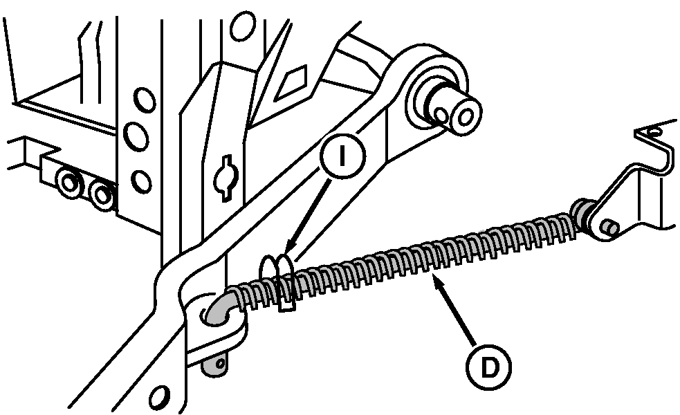
5. Place lever (H) over pin (C), lower channel and fasten with ring (B). 6. For early models equipped with centering stabilizer, remove pin (I) to adjust length of right-hand stabilizer bar (D) as necessary.
|
|
||||||||||||||
OUMX005,00016B6 -19-22MAR05-1/1 |