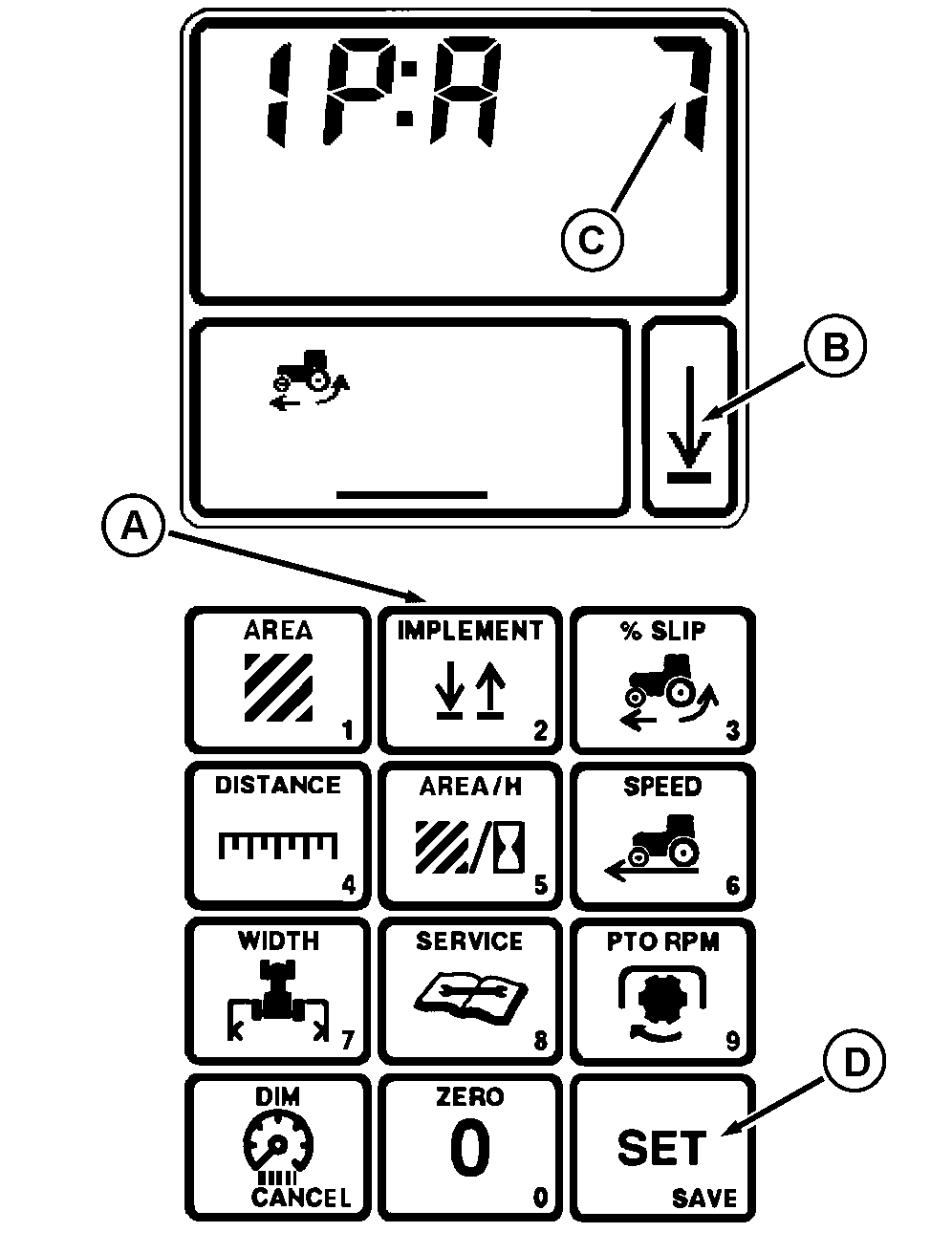
Performance Monitor-Operation and CalibrationIMPLEMENT: Press the IMPLEMENT switch (A) to change implement indicator arrow (B) to the "up" or "down" position. When the implement indicator arrow points down, all measurement functions are engaged. The indicator arrow can be controlled by an optional, external implement switch. (See your John Deere Dealer.) NOTE: An optional implement mounted switch is available from your John Deere Dealer. Implement Selector Calibration:Procedure coordinates the position of the indicator arrow (B) to the position of the hitch or implement switch. 1. Hold IMPLEMENT switch (A) four seconds to change the function code (C).Display will show "IP:" and a function code (3, 7, 8, 13 or 32). This number indicates which device controls the implement arrow (B).
|
|
RW24911,0000123 -19-01AUG01-1/2 |
|
NOTE: If switch (A) does not control the indicator arrow, "7" has not been selected as a function code. For applications which use the hitch sensor or implement switch exclusively, use "3" or "7". A "0" or any other number other than the above will completely shut off the "implement" function. 2. Press SET/SAVE switch (D). Input 3, 7, 8, 13 or 32 using touch pad, then press SET/SAVE switch again. |
RW24911,0000123 -19-01AUG01-2/2 |
