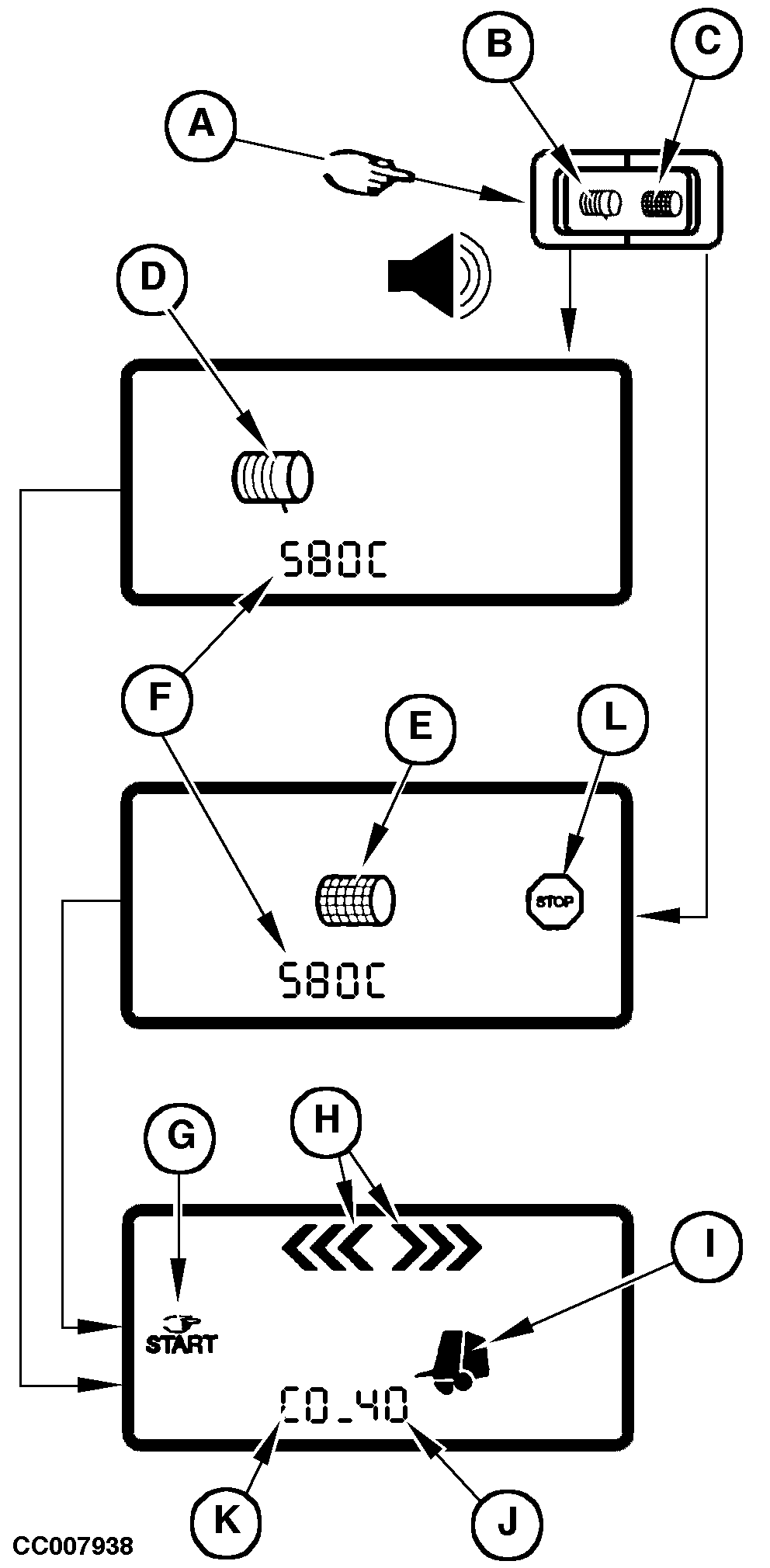
Switching ON Control Monitor in Operating ModeSwitch ON the monitor using the switch (A) located at the rear of the box. This switch has three positions. Choose the twine (B) or the net (C) position to switch ON the monitor. When the monitor is switched ON a beep is heard and LCD screen displays the following pictograms and digits:
NOTE: A baler model with "C" suffix corresponds to a model equipped with precutter device. The screen is then cleared and the following pictograms appear:
IMPORTANT: If display is not as described above, refer to "Malfunction Check-up At Start Up" in this Section. NOTE: The digits (J) are showing the bale diameter (determined by the tension arm position) which is about 0.40 m (1 ft 3.7 in) with the baler empty, or the real bale diameter with a bale in the machine.
|
|
CC03745,00001CD -19-08NOV00-1/1 |
