Changing Precutter Knife Support Position
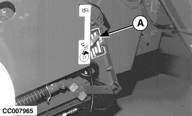
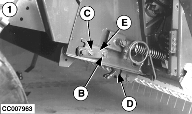
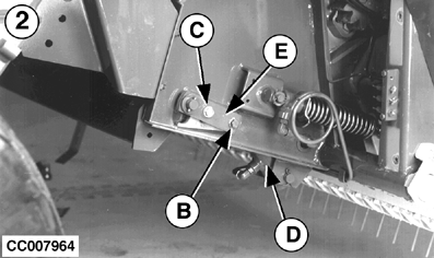
Knife support can be set in two positions: Setting the support in lower position (1) will give a "Regular" quality of cut. Setting the support in upper position (2) will give a "Better" quality of cut. On the other hand the horsepower requirement will be higher. Changing From Lower to Upper PositionSelect "retract knives" precutter operating mode (see "Retracting Or Engaging Precutter Knives" in "Operating BaleMaster Control" Section). Make sure that knives are in cutting position (not retracted). NOTE: To get better access to the left-hand pivoting strap pivot screw (B) pull knife locking lever out of its locking pin and lower it. Slightly loosen pivot screw (B) and remove fixing screw (C) on each side. Act on SCV lever to retract precutter knives. Hydraulic cylinder (D) will extend thus forcing pivoting strap (E) to reach upper position (2). Close shut-off valve (A) as shown. Install and tighten fixing screw (C) then tighten pivot screw (B) as well on each side. Open shut-off valve (A). |
|
CC,570RB004002 -19-15SEP98-1/2 |
|
Changing From Upper to Lower Position
Select "retract knives" precutter operating mode (see "Retracting Or Engaging Precutter Knives" in "Operating BaleMaster Control" Section). Check that knives are not in cutting position (retracted). NOTE: To get better access to the left-hand pivoting strap pivot screw (B) pull knife locking lever out of its locking pin and lower it. If knives are in cutting position (not retracted), act on SCV lever to retract precutter knives. Hydraulic cylinder (D) will extend thus forcing pivoting strap (E) to stay in upper position (2). Close shut-off valve (A) as shown. Slightly loosen pivot screw (B) on each side. Remove fixing screw (C) on each side then open shut-off valve (A). Slowly release hydraulic cylinder pressure to allow the pivoting strap (E) to go down to the lower position (1). Install and tighten fixing screw (C) then tighten pivot screw (B) as well on each side. NOTE: If necessary, put knives back in cutting position.
|
|
CC,570RB004002 -19-15SEP98-2/2 |
 CAUTION:
DO NOT TAKE CHANCES. To avoid severe injury by being pinched by swinging parts always close and open shut-off valve (A) in the following sequence.


