Adjusting Side Gauge ShoesNOTE: Adjusting tilt control cylinder will affect cutting height in all gauge shoe positions. (See Settings for Various Crop Conditions in this section.) Change cutting height by adjusting side gauge shoes. 1. Raise platform using tractor hydraulics. 2. Shut off tractor engine.
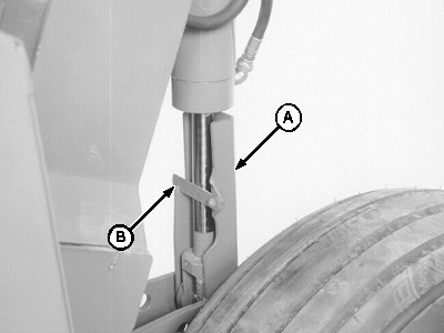
NOTE: If platform is to be in the raised position for an hour or more, lower platform onto cylinder locks. This prevents the transfer of oil from the master cylinder to the slave cylinder causing hydraulic lock and preventing platform from being raised. 3. Engage cylinder lock (A) and retain with strap (B). Repeat on other side.
|
|
OUCC006,0000287 -19-08NOV00-1/3 |
|
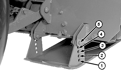
IMPORTANT: Install pins with drilled holes to the inside. Use cotter pins ONLY to fasten drilled pins. Quick-locking pins can be removed by crop and cause loss of gauge shoe resulting in machine damage. NOTE: The two side shoes are in constant contact with the ground. The center gauge shoe(s) protect cutterbar from digging in the ground when operating in uneven terrain. Center gauge shoe(s) are factory installed in the fully raised position and should not be adjusted. 4. Remove two drilled pins and cotter pins from side gauge shoe. Position gauge shoe in desired setting. (See Settings for Various Crop Conditions in this section.) 5. Reinstall drilled pins with holes to the inside of gauge shoe. Fasten with cotter pins. 6. Adjust other side gauge shoe. 7. Start tractor engine. Raise platform using tractor hydraulics. |
|
OUCC006,0000287 -19-08NOV00-2/3 |
|
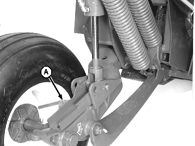
8. Move cylinder lock (A), at each cylinder, to unlocked position. 9. Lower platform using tractor hydraulics. 10. Shut off tractor. 11. Adjust platform float. (See procedure in this section.)
|
|
OUCC006,0000287 -19-08NOV00-3/3 |
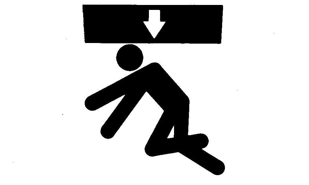
 CAUTION:
Engage BOTH cylinder locks when working on machine. Failure to do so can result in personal injury or machine damage.


