Adjusting Tongue to Tractor DrawbarTo meet all tractor drawbar hitch configurations the tongue is adjustable. IMPORTANT: Before adjusting the tongue, be sure that:
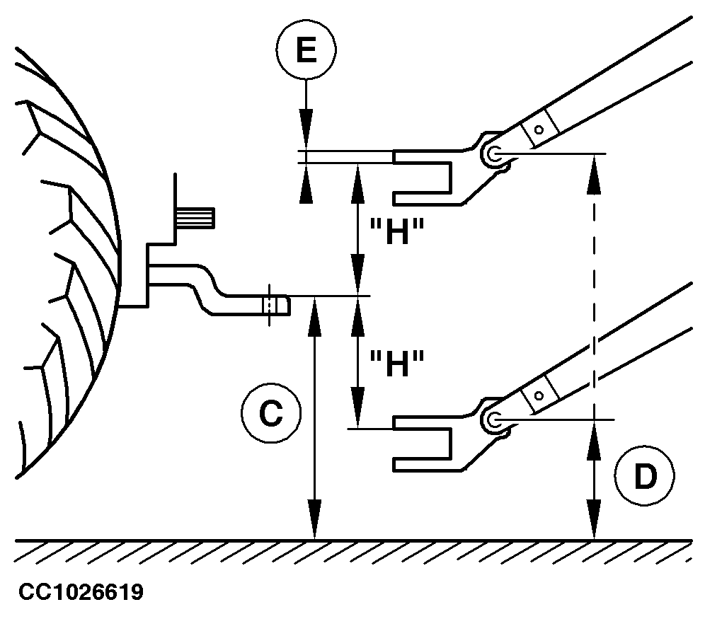
2. Detach baler from tractor. 3. Install a spirit level (A) on gate reinforcement (B). 4. Adjust baler in horizontal position using the spirit level and the jackstand. 5. Measure distance (C). 6. Measure distance (D). 7. Calculate and record the value "H": H = (D) - (E) - (C)
Specification
NOTE: (E) is the correction for the front clevis height. 8. Calculate and record the value "T": T = H / 140 mm (5.5 in.) T is the number of tongue frame teeth to jump. T must be rounded to the closer unit. |
|
CC03745,0000AC3 -19-07JUN05-1/4 |
|
9.
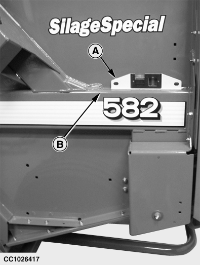
Remove shield (A) screws.
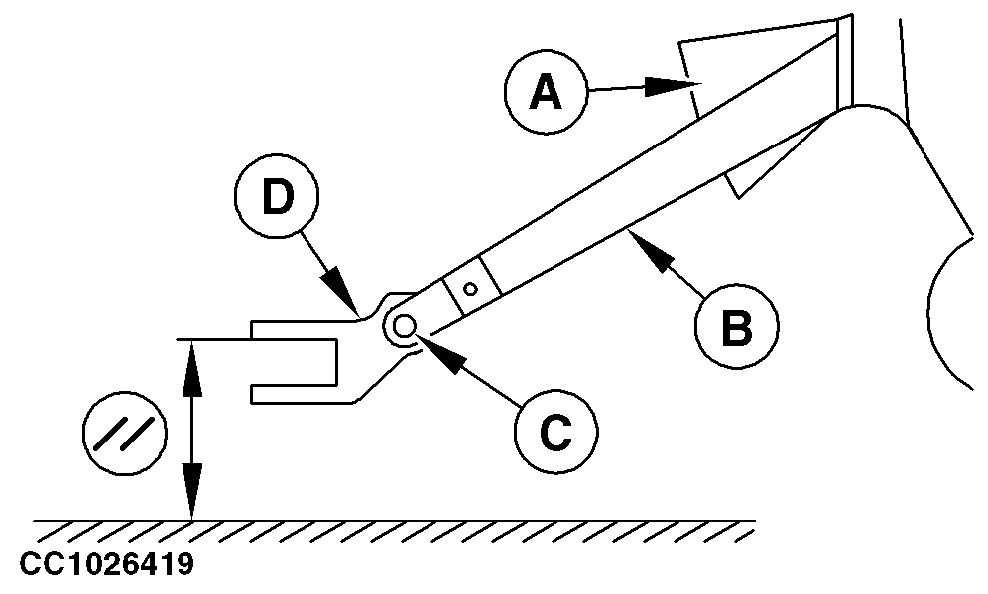
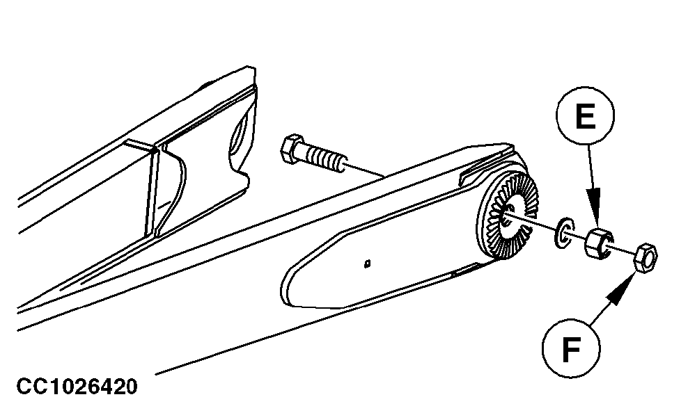
10. Remove front clevis (D). 11. Draw a mark between the frame and each tongue frame. 12. Remove lock nut (F) from left tongue frame (B). 13. Loosen nut (E). 14. Raise or lower tongue frame by "T" teeth, using the mark as a start point. 15. Tighten nut (E). 16. Repeat step 12 to 15 to adjust the right hand tongue frame. 17. Check that the two tongue frames are at the same level. 18. Install front clevis (D). 19. Set front clevis (D) as horizontal as possible with baler attached to the tractor. 20. Tighten tongue frame fixing nuts (E), lock nuts (F) and front clevis fixing screw (C) to specified torque. Specification
|
|
CC03745,0000AC3 -19-07JUN05-2/4 |
|
NOTE: Make sure that all rings are engaged (not standing tip to tip) when tightening screw (C) and nuts (E) and (F). IMPORTANT: Slowly and carefully perform a short test with baler attached to the tractor and check that there is absolutely no interference between tongue frame (B) and hook-up in short turns, otherwise major damage on hook-up will occur. |
CC03745,0000AC3 -19-07JUN05-3/4 |
|
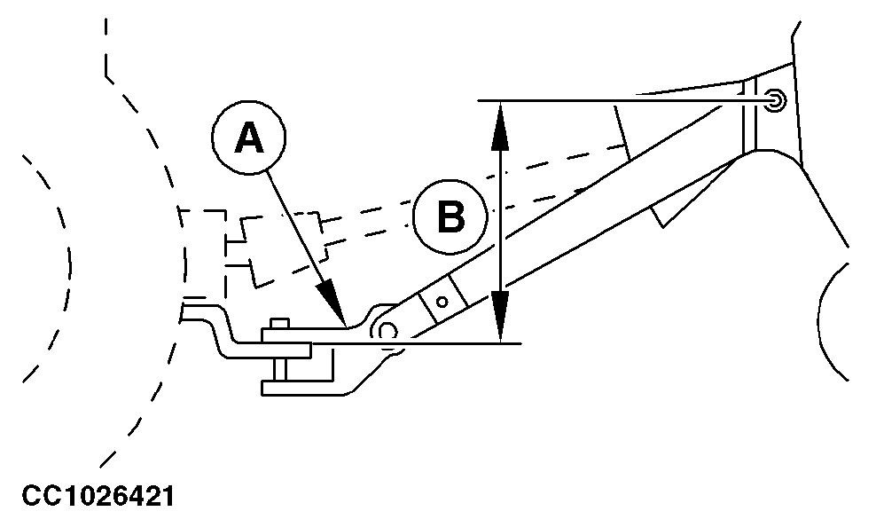
IMPORTANT: Maximum allowed offset (B) between tongue base articulation and front clevis (A) should meet specification. Specification
21. If necessary, modify the wheel spindles position or if the drawbar is angled, turn it upside down to increase the front clevis height. 22. Adjust bale discharging ramp. (See "Adjusting Bale Discharging Ramp" in this section.) |
|
CC03745,0000AC3 -19-07JUN05-4/4 |