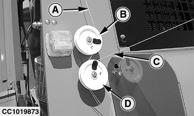
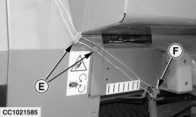
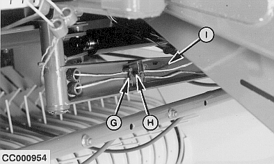
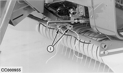
Routing Twine Through GuidesLoop twine (A) from right-hand side twine box around pulley (B) and twine (C) from left-hand or front twine box around pulley (D). IMPORTANT: If only one twine is used on balers equipped with BaleTrak control monitor and twine sensors installed, loop this twine around both pulleys (B) and (D) so that the monitor can detect the presence of two twines and then react properly (monitor is set for the use of two twines). If this is not done, one of the pulleys is not rotating which the monitor will interpret as a twine not being caught during tying cycle and thus will display warning messages on LCD screen. Route twines through guides (E) and (F). Loop twines between guide pins (G) and place twines under tension plate (H) as shown. Thread twines through twine arm (I). There must be 300 mm (12 in.) of twine exposed from end of twine arm.
|
|
OUCC006,000066E -19-29APR02-1/1 |


