Twine Tying Cycle
The twine tying cycle is as follows:
-
Initial Position of Knotter
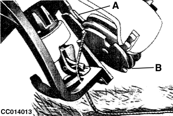
CC014013-UN-22OCT98A - Twine Holder
B - Twine Disk
Twine is held in twine disk (B) by twine holder (A). As the bale is formed, it pulls twine from the twine box.
-
Twine Holding
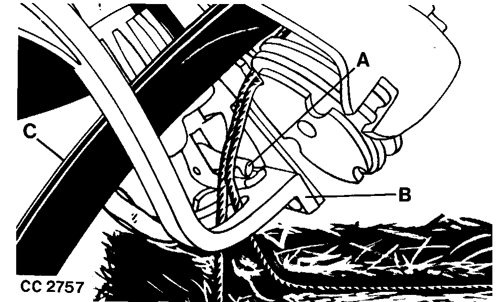
CC2757-UN-23SEP98A - Billhook
B - Knife Arm
C - Needle
When the bale reaches its proper length, the measuring wheel trips the tying mechanism. With the help of the tucker finger, needle (C) brings the second strand of twine through guide on knife arm (B), across billhook (A) and into the twine disk.
-
Start of Tying
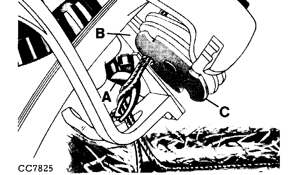
CC7825-UN-25SEP98A - Billhook
B - Twine Holder
C - Twine Disk
Billhook (A) starts its revolution when the gear teeth on the intermittent knotter gear have operated the disk drive pinion and turned the disk sufficiently to permit twine holder (B) to secure both strands of twine in disk (C).
-
Prepare the Knot
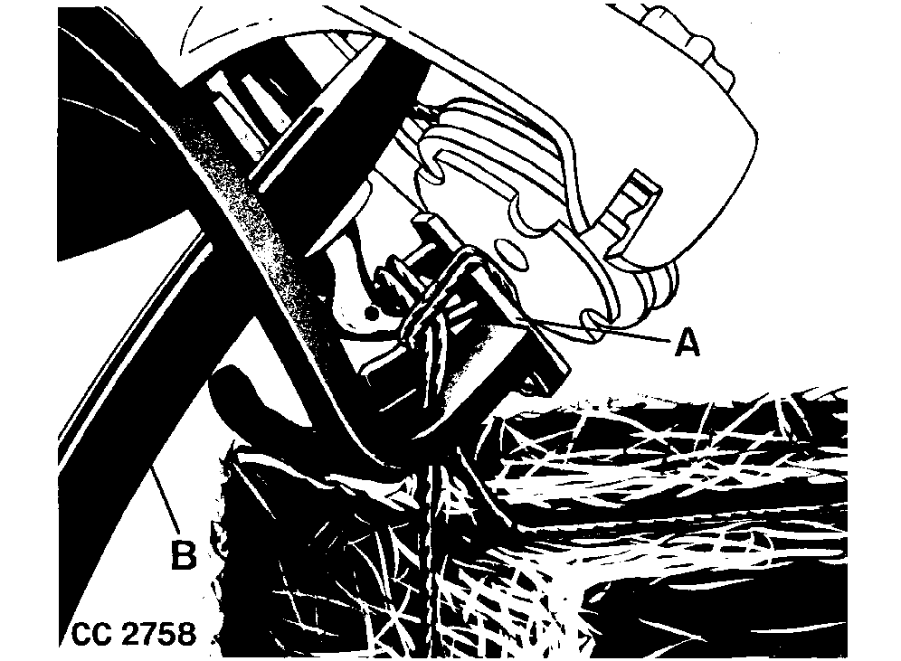
CC2758-UN-23SEP98A - Knife
B - Needle
As the billhook turns, it forms a loop of twine around the hook and the jaw opens to receive the twine. Knife (A) moves forward, ready to cut the twine between billhook and disk.
At this stage, needle (B) begins to retract, leaving the twine in the disk which will be held there for the next knot.
-
Cut the Twine
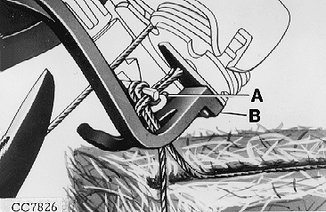
CC7826-UN-23SEP98A - Wiper
B - Knife Arm
Billhook jaw has now closed and holds the ends of the twine tightly. The twine has been cut and wiper (A) on knife arm (B) wipes looped twine from the outside of the billhook to complete the knot.
-
End of Tying
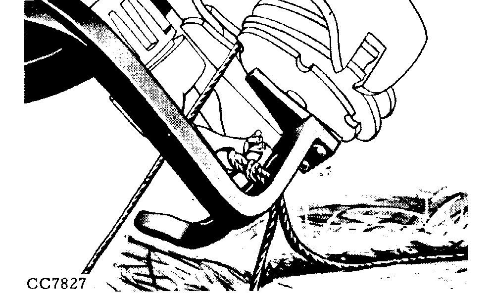
CC7827-UN-25SEP98The tied knot drops from the billhook.
The needles then return to the ”home” position, leaving the strand of twine in the disk and extending through the bale case ready to receive material for the next bale, at the end of which another tying cycle begins.
|
OUCC002,00022AD-19-20100316 |