Adjust Twine Disk
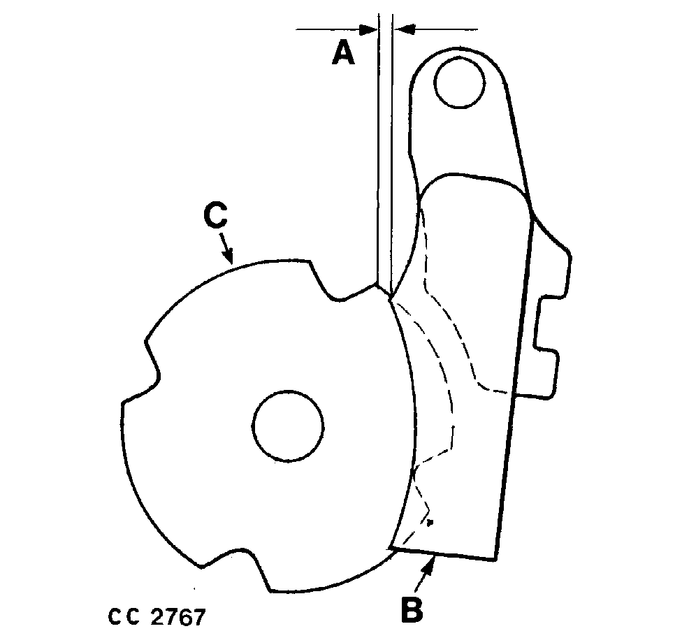
CC2767-UN-23SEP98
A - 0.5—1.5 mm (0.02—0.06 in.)
B - Twine Holder
C - Center Twine Disk
NOTE: Make this adjustment after tying a minimum of two bales and with twine still in twine disk.
Twine disk adjustment is determined by the position of notches in twine disk (C) relative to twine holder (B).
The right corner of the notch in the twine disk center plate must be 0.5—1.5 mm (0.02—0.06 in.) (A) to the left twine holder edge (with twine in twine disk).
Adjust Twine Disk Position:
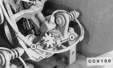
CC9150-UN-23SEP98
A - Nut
B - Twine Disk
-
Loosen nut (A). Do not remove nut. Tap nut end of shaft to break tapered joint loose.
-
Move twine disk (B) to desired location.
-
Tap pinion end of shaft.
-
Rotate worm gear counterclockwise until seated. Tighten nut (A).
NOTE: End play must be 0.12—0.38 mm (0.005—0.015 in.).
|
OUCC002,0002318-19-20100326 |