Attach Implements with Euro or Combi Euro/SMS Carrier
 CAUTION: To prevent serious injury, DO NOT allow bystanders
near loader while attaching implement. ONLY tractor operator is allowed
to attach implement.
-
Clean debris from latching mechanism, carrier, and attaching points.
NOTE: 3rd function multicoupler lever must be in locked (DOWN) position and cover must be closed when implement multicoupler is disconnected.
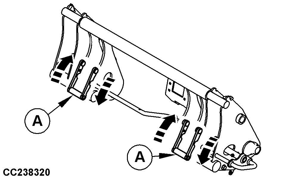
CC238320-UN-18MAY15Combi Euro/SMS Carrier Shown
A - Movable Spacer
For loaders equipped with Euro carrier, go to step 3.
-
On loaders equipped with Combi Euro/SMS carrier, place spacers (A) according to the implement type:
- For Euro implement, place spacer (A) in low position as shown.
- For SMS implement, place spacer (A) in high position.
-
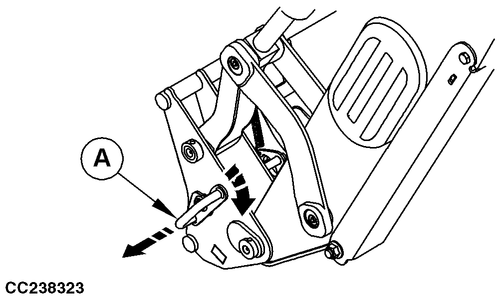
CC238323-UN-26MAY15Loaders without Hydraulic Implement Unlatching
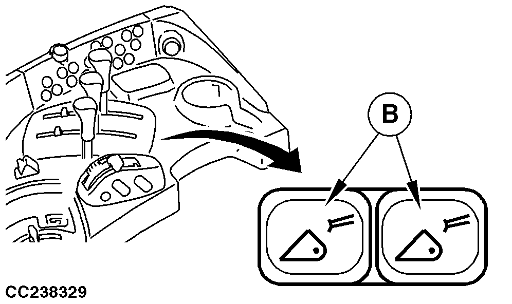
CC238329-UN-26MAY15Loaders with Hydraulic Implement Unlatching
A - Handle
B - Unlatching Button
Place implement latch in unlatched position:-
Loaders without hydraulic implement unlatching:
- Place transmission in PARK, shut off engine and remove key.
- Pull latch handle (A) outwards and rotate clockwise until it is locked in unlatched position.
-
Loaders with hydraulic implement unlatching:
- Fully roll back carrier to raise pressure in the accumulator of hydraulic implement unlatching.
- Simultaneously press both buttons (B) to move implement latch to unlatched position.
NOTE: On some tractor models, unlatching button is positioned on the radio console.
If hydraulic implement unlatching is out of order, the system can be used manually.
-
-
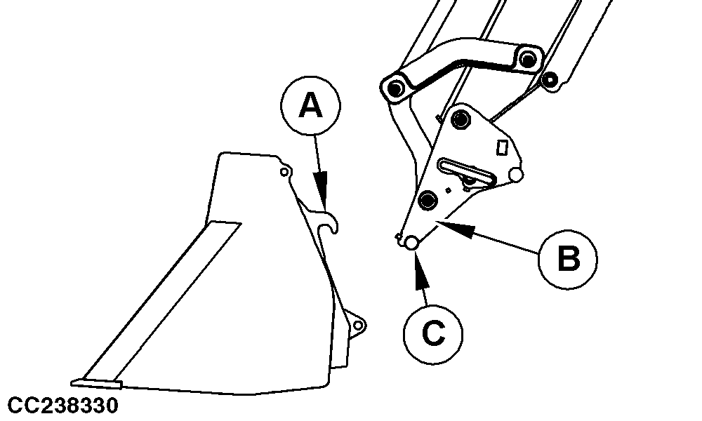
CC238330-UN-12MAY15A - Hook
B - Arm
C - Carrier Hooking Bar
Attach Implement:-
Dump carrier as shown.
-
Drive forward and align carrier hooking bar (C) under implement hooks (A).
-
Raise carrier until carrier hooking bar (C) engages in hooks (A) on both sides.
-
-
Latch Implement:
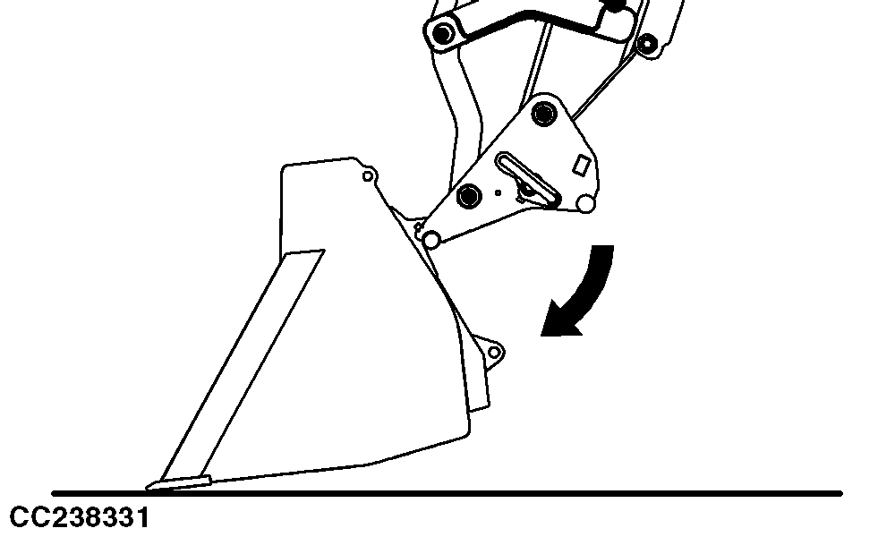
CC238331-UN-02JUN15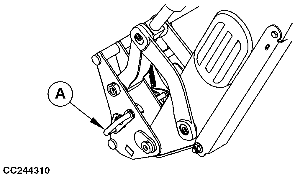
CC244310-UN-02JUN15A - Latch Handle
 CAUTION: Avoid injury from unexpected implement movement while
attaching. If loader is raised prior to implement latching, the implement
may jump off the carrier bar and contact a bystander. To avoid unexpected
detachment, roll carrier back slowly until implement latch engages
before lifting loader.
CAUTION: Avoid injury from unexpected implement movement while
attaching. If loader is raised prior to implement latching, the implement
may jump off the carrier bar and contact a bystander. To avoid unexpected
detachment, roll carrier back slowly until implement latch engages
before lifting loader.Slowly roll back carrier until implement latch engages.
-
Check that implement is properly latched on loader.
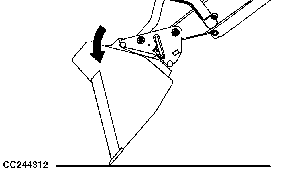
CC244312-UN-02JUN15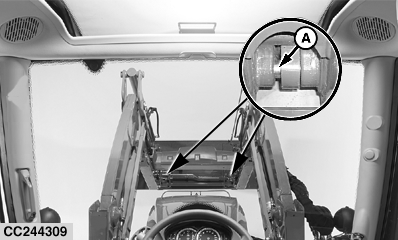
CC244309-UN-02JUN15A - Latch Pin (1 on each side)
 CAUTION: To avoid serious bodily injury or death, DO NOT operate
loader before making sure latch pins (A) are properly engaged with
implement. Failure to engage pins could cause implement to detach
from loader.
CAUTION: To avoid serious bodily injury or death, DO NOT operate
loader before making sure latch pins (A) are properly engaged with
implement. Failure to engage pins could cause implement to detach
from loader.Check pin engagement with implement:
-
Position loader approximately 300 mm (1 ft.) above ground and dump implement until front edge contacts ground.
-
Apply pressure against ground (extend bucket cylinders) to verify that pins (A) are fully engaged in implement.
-
-
Lower loader to ground, place transmission in PARK, shut off engine, and remove key.
-
Relieve pressure in hydraulic system. See your tractor Operator’s Manual for specific procedure.
-
Lock out joystick. See Lock and Unlock Joystick in Controls section. If equipped with other loader control levers, see your tractor Operator’s Manual.
-
Connect implement hydraulics and electrics (implement with 3rd or 4th function).
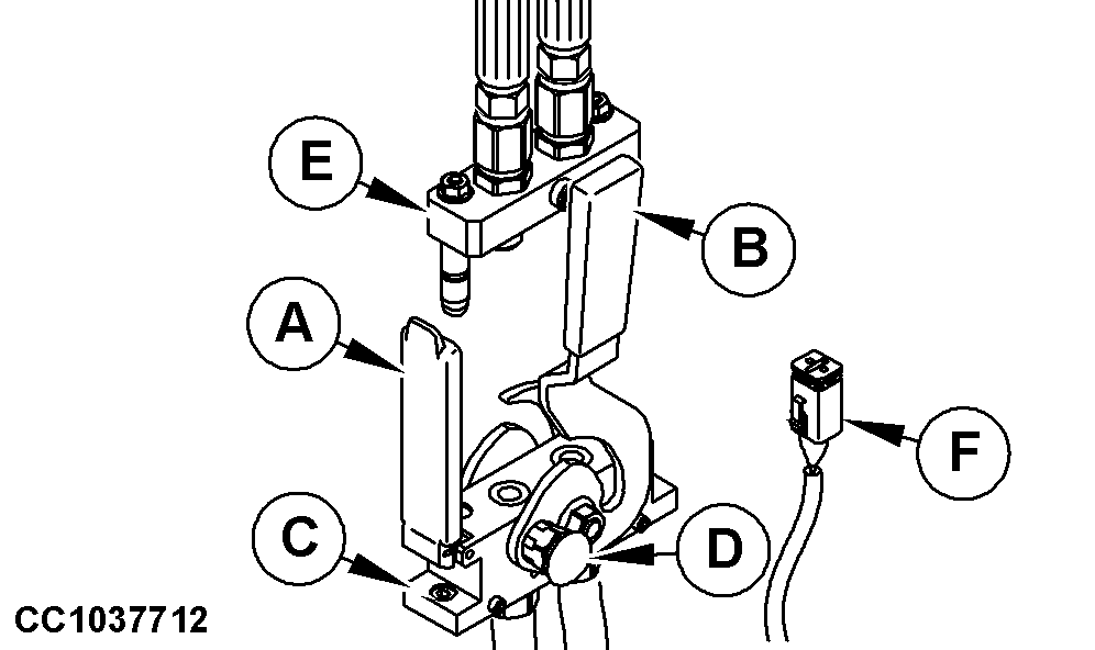
CC1037712-UN-17JUL12Implement Multicoupler
A - Cover
B - Lever
C - Base
D - Lock Button
E - Top Case
F - Harness
NOTE: Before each connection, carefully clean the mating surface of base and top case, as well as guiding pins.
Open multicoupler cover (A), push lock button (D) and simultaneously pull up lever (B).
IMPORTANT: Multicoupler must align properly or damage to couplers may occur.
Engage top case (E) on base (C). Pull down lever (B) until lock button (D) engages, so that top case (E) is connected to base (C).
Connect electrical harness (F) for additional functions if equipped.
-
Unlock joystick.
-
Check implement operation.
|
NB02380,000012A-19-20160414 |