Check and Adjust Engine Valve Clearance (3029 Engines)

CD30544-UN-19MAY98
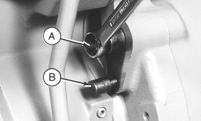
Lock Engine at Top Dead Center
A - Flywheel Turning Tool
B - Timing Pin
Adjust engine valve clearance as follows or have your authorized servicing dealer or engine distributor adjust the engine valve clearance.
-
Remove rocker arm cover and crankcase vent tube.
-
Using JDE83 or JDG820 Flywheel Turning Tool (A), rotate engine flywheel in running direction (clockwise viewed from water pump) until No. 1 piston (front) has reached top dead center (TDC) on compression stroke. Insert timing pin JDE81-4 (B) into flywheel bore.
-

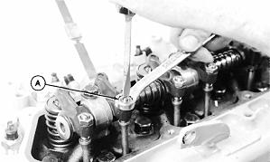
RG6307-UN-03AUG92Adjust Valve Clearance

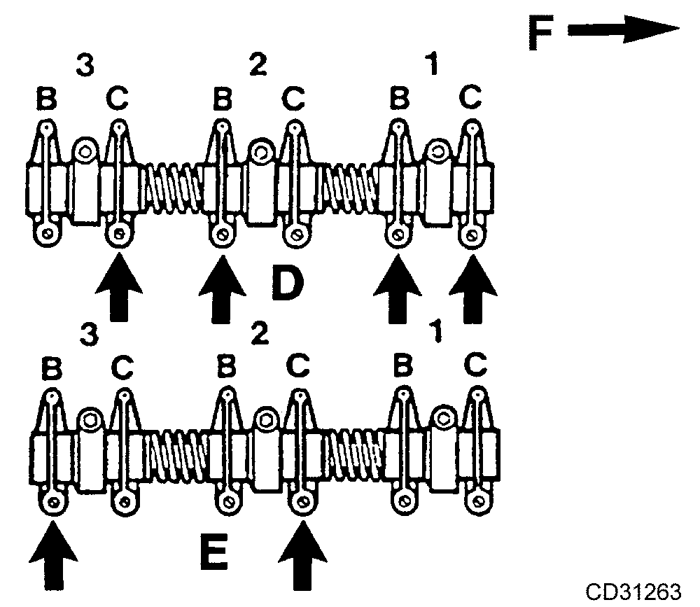
CD31263-UN-16DEC10Valve Clearance Adjustment on 3029 Engines
A - Adjusting Locknut
B - Exhaust Valve
C - Intake Valve
D - No. 1 Piston at TDC Compression Stroke
E - No. 1 Piston at TDC Exhaust Stroke
F - Front of Engine
Check and adjust valve clearance to specifications according to the following procedure:NOTE: Firing order is 1-2-3
-
Lock No. 1 piston at TDC compression stroke (D).
-
Adjust valve clearance on No. 1 and 2 exhaust valves and No. 1 and 3 intake valves.
-
Rotate flywheel 360°. Lock No. 1 piston at TDC exhaust stroke (E).
-
Adjust valve clearance on No. 3 exhaust valve and No. 2 intake valve.
Item Measurement Specification Valve Clearance (Engine Cold) Intake 0.35 mm (0.014 in.)
-
-
If valves need adjusting, loosen the locknut on rocker arm adjusting screw. Turn adjusting screw until feeler gauge slips with a slight drag. Hold the adjusting screw from turning with screwdriver and tighten locknut (A) to 27 N˙m (20 lb.-ft.). Recheck clearance after tightening locknut. Readjust clearance as necessary.
-
Reinstall rocker arm cover and crankcase vent tube.
|
CD03523,00002C8-19-20101223 |