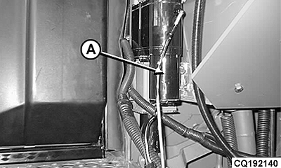
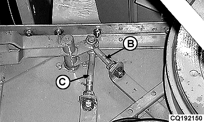
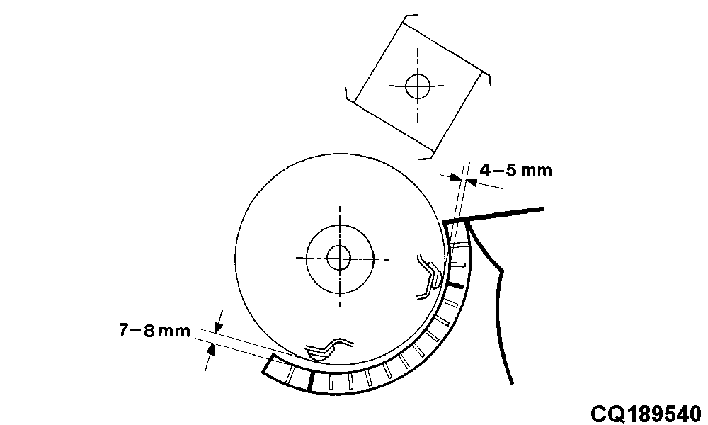
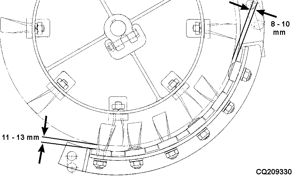
Concave and Cylinder Clearance AdjustmentBefore adjusting the concave and cylinder clearance by the electrical system from the cab, what is called fine adjustment is necessary. The electrical actuator (A) should be completely closed so that the clearance between concave and cylinder is minimum. The infotrak monitor should display a concave clearance of "4". By means of the pin (B) adjust the rear part of the concave and with pin (C) adjust the front part of the concave. Rear clearance:
Front clearance:
IMPORTANT: Carry out adjustment on both sides of combine. NOTE: This adjustment should always be done when changing concave. NOTE: All further clearance adjustments must be made via the switch in the cab. See "Controls and Instruments" section. |
|
AG,CO03622,1652 -19-22JUL04-1/1 |