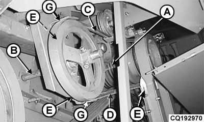
Adjusting Unloading System DriveLeft-hand side of combine: NOTE: To avoid accidents shut off engine before adjusting belt guide. The system is driven by belt (C) from the engine pulley (A) and jackshaft (B). Adjust belt guide (D) with supports (G) after loosening bolts (E) to obtain uniform spacing of 3 to 5 mm (0.1 to 0.2 in.) between the belt and guide with the belt tightened. Run machine and verify the adjustment between belt and guide. |
|
AG,CO03622,2152 -19-26SEP03-1/2 |
|
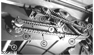
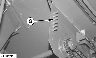
Sprocket (B) is engaged by jackshaft (A) on the right-hand side of the combine. Chain tension is adjusted with idler sprocket (D). Loosen hex nut (E) and position the idler sprocket accordingly, with bolt (F). IMPORTANT: Bolt (G) is a shear bolt which will break in order to protect the drive system. Always replace with an original JOHN DEERE part. Tighten it enough to bring the drag arm smoothly in contact with sprocket (H). Tighten shear bolt (G) using a screwdriver while holding lock nut with a spanner. NOTE: Six (6) replacement shear bolts (G) are supplied with the combine.
|
|
AG,CO03622,2152 -19-26SEP03-2/2 |