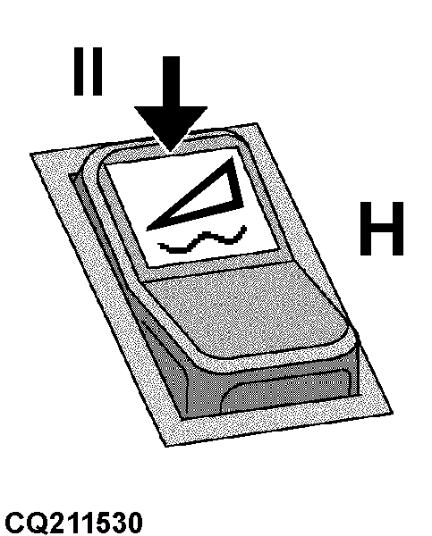
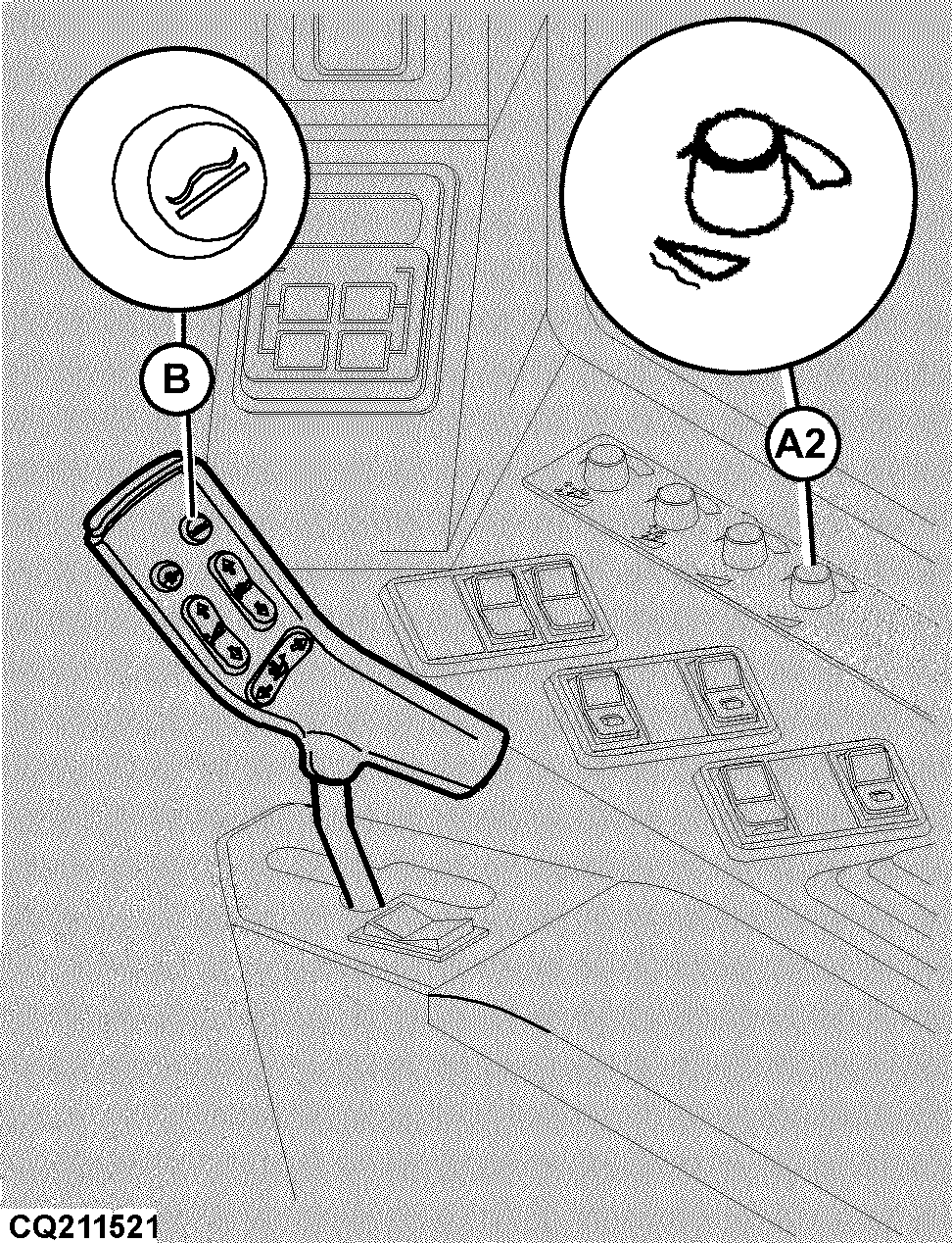
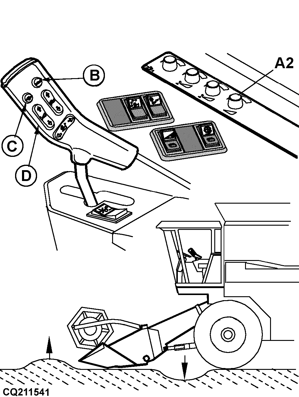
Automatic Float Control for 300 and 600-CWS/WTS series Rigid HeadersIMPORTANT: The float system must be calibrated. See "Header Calibration Procedure" in the Service - Electrical System section. Requirements: ·Engine running (high speed) to enable float. ·Road safety switch in field position. ·Threshing and header engaged. ·Move float enable switch (H) to the position (II). NOTE: Do not adjust header float unless hydraulic oil is at operating temperature. To activate flotation press knob (B). The pressure applied by the header against the ground is adjusted by potentiometer (A2). Float Adjustment: Use potentiometer (A2) to adjust to desired header float. ·Turn clockwise - Increase ground pressure (lower header). ·Turn counterclockwise - Reduce ground pressure (raise header).
|
|
MB03730,00002BA -19-05MAR04-1/2 |
|
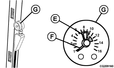
NOTE: When header float knob (B) is activated the automatic height control of the header is deactivated. Operation: Once the system is calibrated, it can be turned "ON" by pushing the resume-to-float knob (B) on the multifunction control handle. The system should lower the header to the position where the float was calibrated, and then open the accumulator shutoff valve in order to effect closed loop lift cylinder pressure control, turning "ON" and "OFF" the header raise/lower valves to keep the lift cylinder pressure set point. It can be tested by driving around on uneven ground and observing the lift cylinder pressure on the pressure gauge (G). With the float set point fully rotated clockwise (A2) the header ground pressure should be almost zero, with the lift cylinder pressure equal to the static weight of the header. With the float set point fully rotated counterclockwise, 40% of the header weight should be on the ground, with lift cylinder pressure equal to 60% of the static weight of the header. Drive over a ditch, or other such very uneven surfaces, and see how the system behaves, in other words if it maintains constant lift cylinder pressure. The system should be fairly fast in responding but not unstable. NOTE: Needle (F) moves to the right when ground pressure (float) drops, and to the left when pressure increases. The autofloat control may be deactivated by pressing knob (D) or activating the header automatic height control knob (C).
|
|
MB03730,00002BA -19-05MAR04-2/2 |