Adjusting Tractor Drawbar
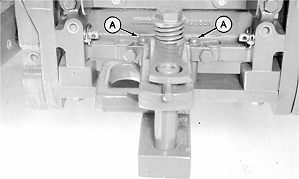
1. Remove locking pins (A) and slide drawbar to center position (shown). 2. Install locking pins. 3. Remove clevis assembly, if equipped. 4. Measure drawbar thickness. Hitch conversion kit is recommended if baler is being operated with a tractor that has a 61 mm (2 in.) thick drawbar. Conversion kit part No. AE57344 is available through John Deere parts. |
|
AG,OUO6017,1205 -19-22SEP99-1/3 |
|
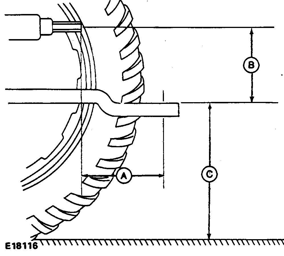
IMPORTANT: If shaft adapter is used to reduce 44 mm (1-3/4 in.) diameter shaft to 35 mm (1-3/8 in.) diameter shaft, measure from end of adapter to drawbar hole. Failure to conform to the following setup dimensions can result in serious powerline damage. 5. If drawbar is offset, turn drawbar so offset is down, as shown. 6. Set drawbar to the following dimensions:
|
|
AG,OUO6017,1205 -19-22SEP99-2/3 |
|
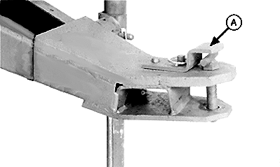
IMPORTANT: To avoid powerline damage when front of tractor "noses" down, there must be a minimum of 76- 89 mm (2.992-3.504 in.) clearance between powerline and top of hitch strap (A). Measure on level ground. If tractor drawbar is too low the following problems may occur:
To increase drawbar height, flip drawbar over (offset up). If tractor drawbar is too high the following problems may occur:
|
|
AG,OUO6017,1205 -19-22SEP99-3/3 |
 CAUTION:
To avoid personal injury, use locking pins to hold drawbar stationary when operating PTO-driven implements.


