Adjusting Front Twine Arm
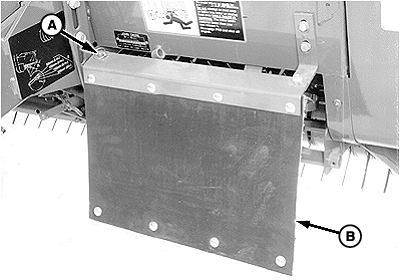
If there is crop material which is holding twine arms from moving freely during twine arm cycle, it is recommended that twine arms be manually positioned to release any "hold" they may have on the crop material. Turn off power to twine arms. This will help to make the unplugging operation easier and prevent twine arms from moving unexpectedly while your hands may be in the path of the twine arms. Stay out of the path of twine arms at all times when power to twine arms is ON. 1. If equipped with MEGATOOTH pickup; Remove quick-lock pin (A) and rotate left-hand curtain (B) away from front frame.2. Move twine arms to "home" position as follows: Hydraulic Twine Wrap; 1. Start tractor engine.2. Operate tractor hydraulics to move twine arm (A) in position. 3. Shut off tractor engine. Remove key. Electric Twine Wrap; 1. Turn tractor key to ON position. Do not start tractor engine.2. Turn monitor-controller ON. 3. Press and momentarily hold TWINE/NET key to select TWINE mode. 4. Press EXTEND or RETRACT key to move twine arm (A) under cutter link support (B). |
|
OUMX005,000006E -19-15APR03-1/3 |
|
|
OUMX005,000006E -19-15APR03-2/3 |
|
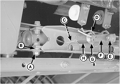
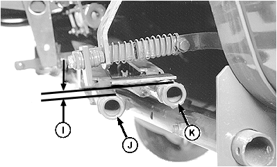
3. Remove cap screw and nut (E), spring-locking pin (D), washer (G), spacer (H), spring (C) and twine spacing strap (F). 4. Measure height difference (I) between tops of twine arms (J and K). Twine arm (K) must be higher than twine arm (J) to within specifications. Specification
5. To adjust distance, loosen nut (A) enough so end of twine arm can be moved manually with some resistance.
6. Tighten nut (A) to specifications. Specification
7. Install twine spacing strap, spring, spacer, washer and nut and bolt. Install spring-locking pin (D) in desired hole.
8. If equipped with a MEGATOOTH pickup; Rotate left-hand curtain toward front frame and secure with quick-lock pin. |
|
OUMX005,000006E -19-15APR03-3/3 |
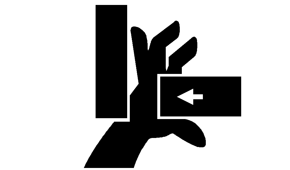
 CAUTION:
Twine arms can move unexpectedly when twine arm power is on. Stay out of the path of twine arms at all times) when twine arm power is on. During service or adjustment procedures for twine arms or twine cutter mechanism, turn off power to twine arms BEFORE placing your hands in the path of twine arm travel.


