Adjusting Twine Cutter-to-Twine Arm
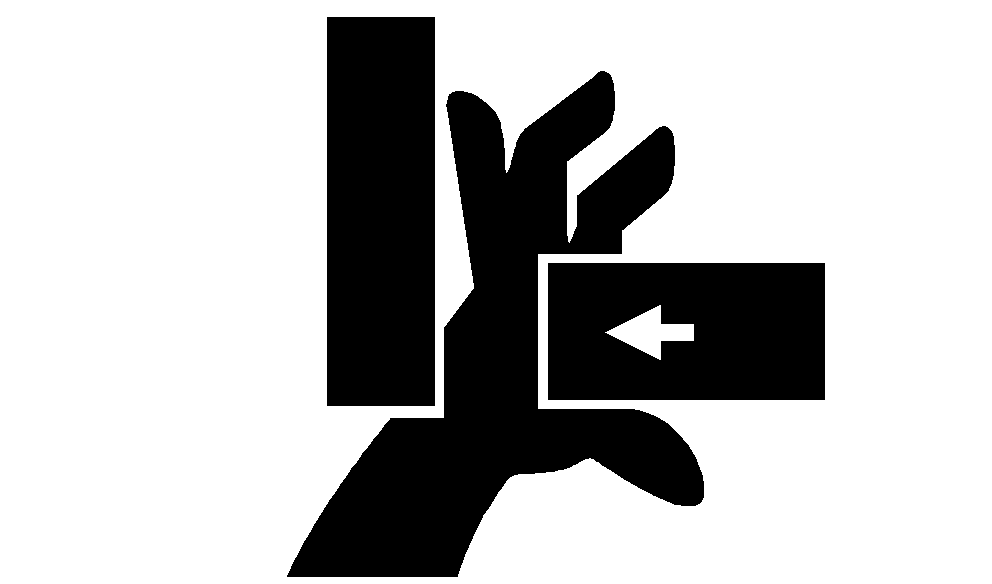
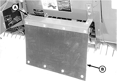
If there is crop material which is holding twine arms from moving freely during twine arm cycle, it is recommended that twine arms be manually positioned to release any "hold" they may have on the crop material. Turn off power to twine arms. This will help to make the unplugging operation easier and prevent twine arms from moving unexpectedly while your hands may be in the path of the twine arms. Stay out of the path of twine arms at all times when power to twine arms is ON. Twine knife has two cutting edges. Be careful when working around the knife. It is sharp. 1. If equipped with a MEGATOOTH™ pickup; Remove quick-lock pin (A) and rotate left-hand curtain (B) away from front frame.2. Remove crop material from knife and hex anvil area.
|
|
OUMX005,000006F -19-02OCT00-1/3 |
|
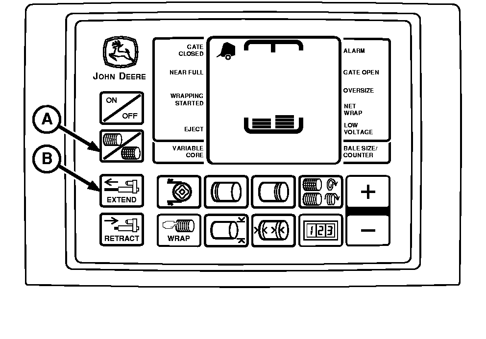
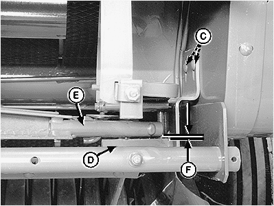
NOTE: Dimension (F) applies to the front arm. Rear arm must clear the bottom of the twine knife. 3. Move twine arms until front twine arm tube (E) is centered over hex anvil (D) as follows: Hydraulic Twine Wrap; 1. Start tractor engine.2. Operate tractor hydraulics to move twine arm in position. 3. Shut off tractor engine. Remove key. Electric Twine Wrap; 1. Turn tractor key to ON position. Do not start tractor engine.2. Turn monitor-controller ON. 3. While in TWINE mode, press monitor-controller EXTEND key (B) to move front twine arm tube until centered over hex anvil. 4. Turn monitor-controller OFF. Turn tractor key to OFF position. Remove key. 4. Open left-hand door and loosen nuts (C). 5. Adjust twine cutter assembly, so clearance (F) between knife hex anvil (D) and twine arm tube (E) is within specifications. Twine cutter bracket should be level (parallel with bottom edge of frame) . Specification
6. Tighten nuts (C). 7. If rear twine arm contacts bottom side of knife support and minimum clearance in Step 5 is obtained, bend twine cutter bracket so hex anvil is parallel to twine arm. 8. Check knife adjustment. (See CHECKING KNIFE ADJUSTMENT in this section.) |
|
OUMX005,000006F -19-02OCT00-2/3 |
| 9. If equipped with a MEGATOOTH pickup; Rotate left-hand curtain toward front frame and secure with quick-lock pin. |
OUMX005,000006F -19-02OCT00-3/3 |
 CAUTION:
Twine arms can move unexpectedly when twine arm power is on. Stay out of the path of twine arms at all times when twine arm power is on. During service or adjustment procedures for twine arms or twine cutter mechanism, turn off power to twine arm) BEFORE placing your hands in the path of twine arm travel.
