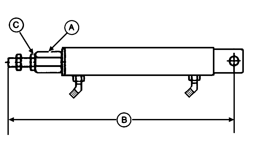
Installing Hydraulic Twine Arm Cylinder-457 and 457S1. Retract cylinder until hex block (A) contacts cylinder barrel. Distance (B) from center of hole in base end of cylinder to end of cylinder rod should be within specifications.Specification
2. Turn hex block (A) on cylinder rod to obtain specifications. Hex block (A) must be contacting cylinder barrel. Tighten jam nut (C). |
|
OUMX005,0000076 -19-02OCT00-1/2 |
|
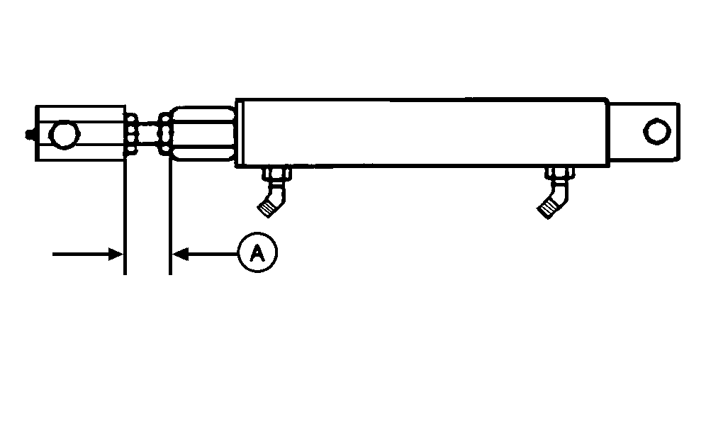
NOTE: If cylinder was removed with end block, see HYDRAULIC TWINE ARM CYLINDER INITIAL LENGTH (BALEWATCH System) in this section for proper installation procedure. 3. Install cylinder on baler by turning cylinder rod into end block until dimension (A) is obtained between end block and hex block to specifications. Specification
The initial cylinder settings should be close to the desired setting for right-hand end wrap placement and twine cutter tension. 4. Install base end of cylinder and fasten with cap screw and lock nut. Do not overtighten, cylinder must be free to pivot. 5. Connect hydraulic hoses. 6. Start tractor engine and operate twine arm through several complete cycles, using tractor hydraulics, to bleed air from cylinder. 7. Adjust position of twine arm to right sidesheet. (See ADJUSTING TWINE ARM DISTANCE FROM RIGHT SIDESHEET-HYDRAULIC [BALEWATCH™ SYSTEM] [457 AND 457S] in this section.) 8. Adjust twine cutter tension. (See ADJUSTING TWINE CUTTER TENSION-HYDRAULIC (BALEWATCH™ SYSTEM) in this section.) |
|
OUMX005,0000076 -19-02OCT00-2/2 |

