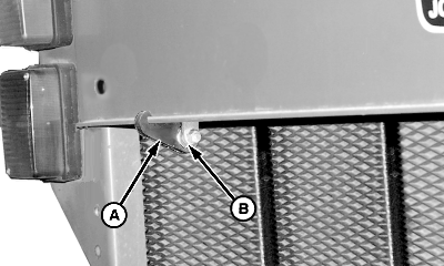
Adjusting Bale Shape Sensor (Channels 007 and 009)NOTE: Number of bale shape indicator "bars" displayed is 24. E97193 Bale Shape Gauge Strap (A) is available through your John Deere dealer. 1. Use E97193 Bale Shape Gauge Strap (A): a. Install strap (A) over roller bearing (B). b. Attach end of strap over baler frame cross-member. Make sure lip of cross-member is seated in notch of Strap. |
|
OUMX005,0000078 -19-25JUN03-1/4 |
|
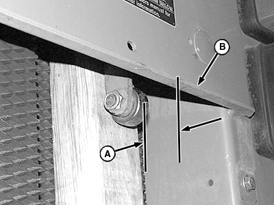
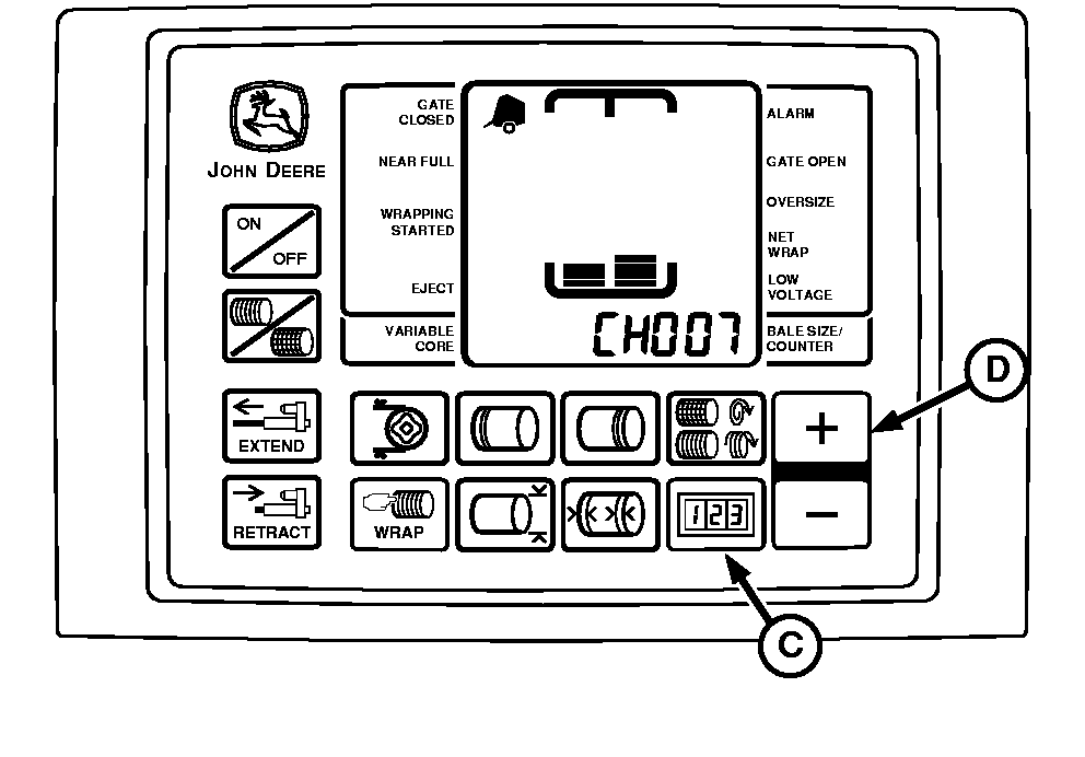
If Bale Shape Gauge Strap (E97193) is not available: a. Put a board approximately 51 x 102 x 457 mm (2 x 4 x 18 in.) between roller bearing and belt as shown. b. Position board to hold bale shape sender arm so rear of roller bearing is 62 mm (2-7/16 in.) (A) from rear edge of panel (B). 2. Press and hold COUNTER key (C) while turning monitor-controller ON. 3. Continue to hold COUNTER key (C) and press PLUS key (D) until:
4. Release COUNTER key (C) to display sensor value. 5. If buzzer does not emit a "setup tone" and display readout is above or below setup value of "176", bale shape sensor (E) is out of adjustment.
|
|
OUMX005,0000078 -19-25JUN03-2/4 |
|
6.
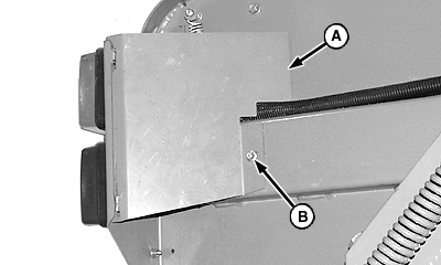
To adjust sensor, remove rolling thread cap screw (B). Rotate shield (A) away from baler.
|
|
OUMX005,0000078 -19-25JUN03-3/4 |
|
7.
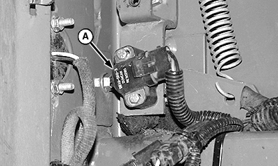
Loosen sensor mounting hardware and rotate sensor (A) until buzzer emits a tone and "176" is displayed. Tighten sensor mounting hardware.
8. Install shield by rotating toward baler and fastening with mounting cap screw. 9. Repeat procedure to adjust opposite side. Use appropriate channel for adjustment.
|
|
OUMX005,0000078 -19-25JUN03-4/4 |
