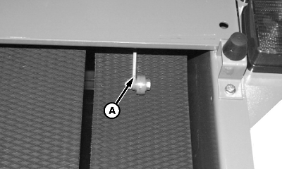
Adjusting Bale Shape Sender1. Close gate completely.2. Engage gate lock. 3. Using tractor hydraulics, raise the belt tension arm to highest position to slacken belts. 4. Shut off tractor engine. 5. Remove lock nut and round-head bolt from tail/warning light shield and rotate shield away from baler. |
OUMX005,0000079 -19-02OCT00-1/4 |
|
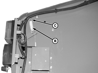
6.
Remove lock nut and washer (C).
7. Push bale shape sender arm (A) forward to disconnect spring (B). 8. Start tractor engine. 9. Lower belt tension arm using tractor hydraulics. Hold hydraulic lever in this position and operate PTO for a few seconds to ensure belts are tensioned. Stop tractor engine.
|
|
OUMX005,0000079 -19-02OCT00-2/4 |
|
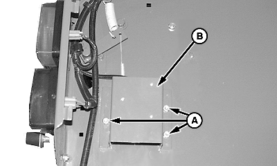
10.
Loosen nuts (A) of shield (B).
|
|
OUMX005,0000079 -19-02OCT00-3/4 |
|
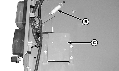
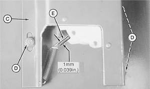
NOTE: Shield (C) has been cut away for illustration purposes only. 11. With roller (A) just contacting belt, move shield (C) up or down as needed to obtain specification between potentiometer arm (E) and bottom stop. Specification
12. Tighten nuts (D). NOTE: Both bale shape indicators on the monitor should show full position at this point (needle pointing toward top dot). If not, see your John Deere dealer. 13. Start tractor engine and raise belt tension arm to slacken belts. 14. Stop tractor engine. 15. Connect spring (B). 16. Rotate tail/warning light shield toward baler and fasten with round-head bolt and lock nut. 17. Start tractor engine and lower belt tension arm.
|
|
OUMX005,0000079 -19-02OCT00-4/4 |