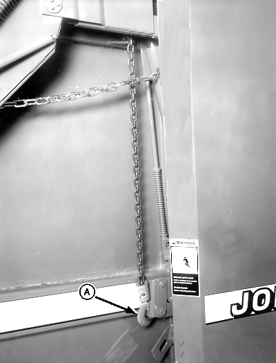
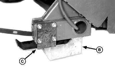
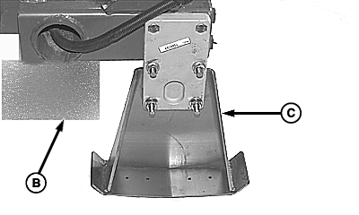
Remove Shipping Skids and Install Wheels (557)1. Attach lifting chain hook under baler frame as shown.2. Using chain hoist, raise one side of baler and put a 229 mm (9 in.) block (B) under baler frame. 3. Remove and discard shipping skid (C). Retain hardware to install spindles.
|
|
OUMX005,0000087 -19-02OCT00-1/4 |
|
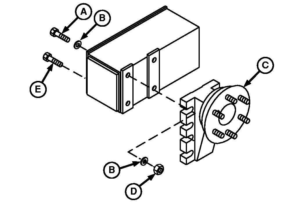
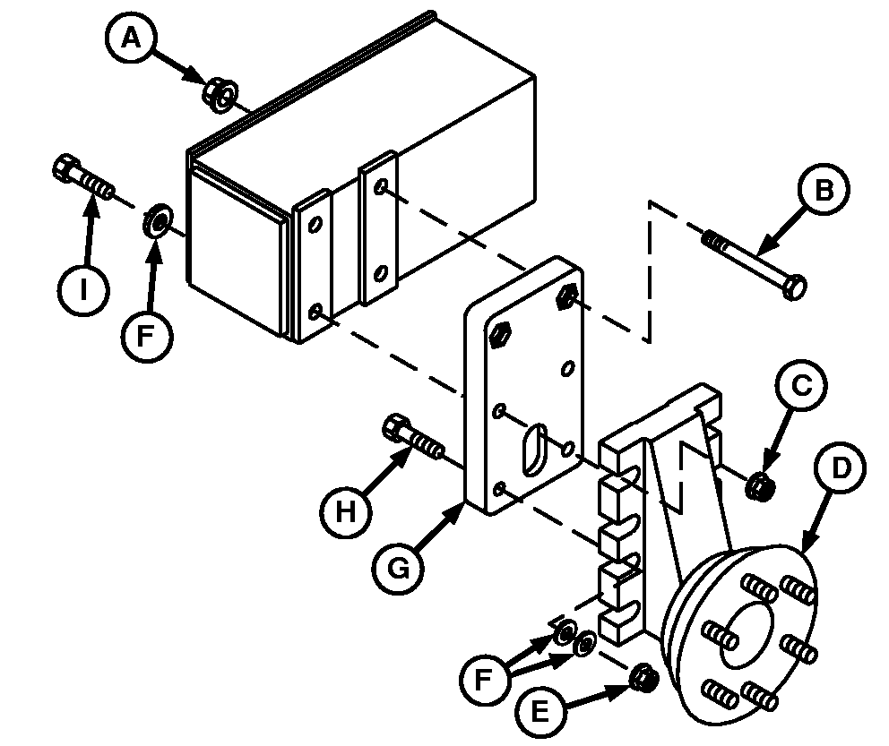
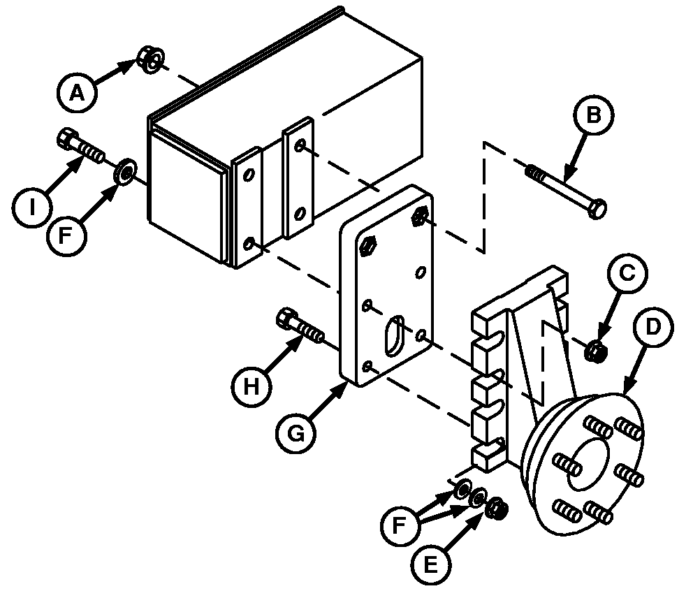
NOTE: Spindle position illustrated is used for most baling conditions. For other crop conditions, refer to WHEEL SPINDLE POSITIONS in Preparing the Baler section of the Operator's manual. 4. Regular or MEGATOOTH™ Pickup: Install spindle with hub offset (C) up. Fasten spindle as follows:
Tighten nuts to specifications. Specification
|
|
OUMX005,0000087 -19-02OCT00-2/4 |
|
MegaWide Pickup: a. Install spacer plate (G) on frame with two M16 x 150 cap screws (B) and nuts (A), if necessary. Tighten nuts to specification. b. Install spindle with hub offset (D) down. Fasten with two M16 x 180 cap screws (I), 17 x 34 x 4 mm washers (F), and nuts (C) as follows:
c. Install two M16 x 80 cap screws (H) through spacer plate (G) and notch in spindle. Install four 17 x 34 x 4 mm washers (F) and two M16 nuts (E). d. Tighten all mounting hardware to specifications. Specification
|
|
OUMX005,0000087 -19-02OCT00-3/4 |
|
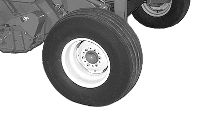
IMPORTANT: Install wheels with 11L-14 tires with valve stems toward the OUTSIDE. Install wheels with 31 x 13.5-15 tires with valve stems toward the INSIDE. Incorrect assembly can cause wheel nuts to loosen. 5. Install wheel with 11L-14 tires with valve stem toward the OUTSIDE. Fasten with six 1/2 in. nuts. Install wheel with 31 x 13.5-15 tires with valve stem toward the INSIDE. Fasten with six 1/2 in. nuts. 6. Tighten nuts to specifications. Specification
7. Repeat procedure on opposite side. 8. Check for proper tire inflation pressure. (See CHECK TIRE INFLATION PRESSURES in this section.) |
|
OUMX005,0000087 -19-02OCT00-4/4 |