Install Gauge Wheels (Regular or MEGATOOTH™ Pickup)
|
|
|
When positioning the gate to provide access for service, always be sure tension arm is fully raised, and against its stops. This is to prevent the gate from rotating downward |
unexpectedly while service work is being performed. ALWAYS raise the gate fully and lower it to the desired opening height before engaging the gate lock. Failure to do this may result in serious injury or death.
1. Start tractor engine and raise gate. 2. Shut off tractor engine and remove key. 3. Rotate interlock lever (B) and move gate lock lever (A) to locked position (shown). |
OUMX005,0000089 -19-02OCT00-1/3 |
|
4.
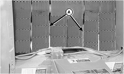
Remove gauge wheels (A).
5. Move gate lock lever to unlocked position. 6. Start tractor engine and lower gate completely. 7. Shut off tractor engine and remove key. 8. Open right-hand side door and remove hardware package from twine box.
|
|
OUMX005,0000089 -19-02OCT00-2/3 |
|
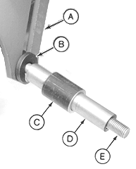
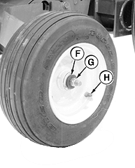
NOTE: Left-hand gauge wheel shown. Installation procedure is similar for both left and right-hand gauge wheels. 9. Insert M16 x 180 cap screw (E) through slot in arm (A). 10. Install 1-5/8 in. washer (B), spacer (C), and bushing (D) on cap screw (E) as shown. 11. Install wheel on spindle assembly with valve stem (H) toward outside. 12. Install 1-5/8 in. washer (F) and lock nut (G). 13. Repeat procedure for opposite side. 14. Adjust gauge wheels. (See ADJUSTING GAUGE WHEELS in Operating the Baler section.) |
|
OUMX005,0000089 -19-02OCT00-3/3 |
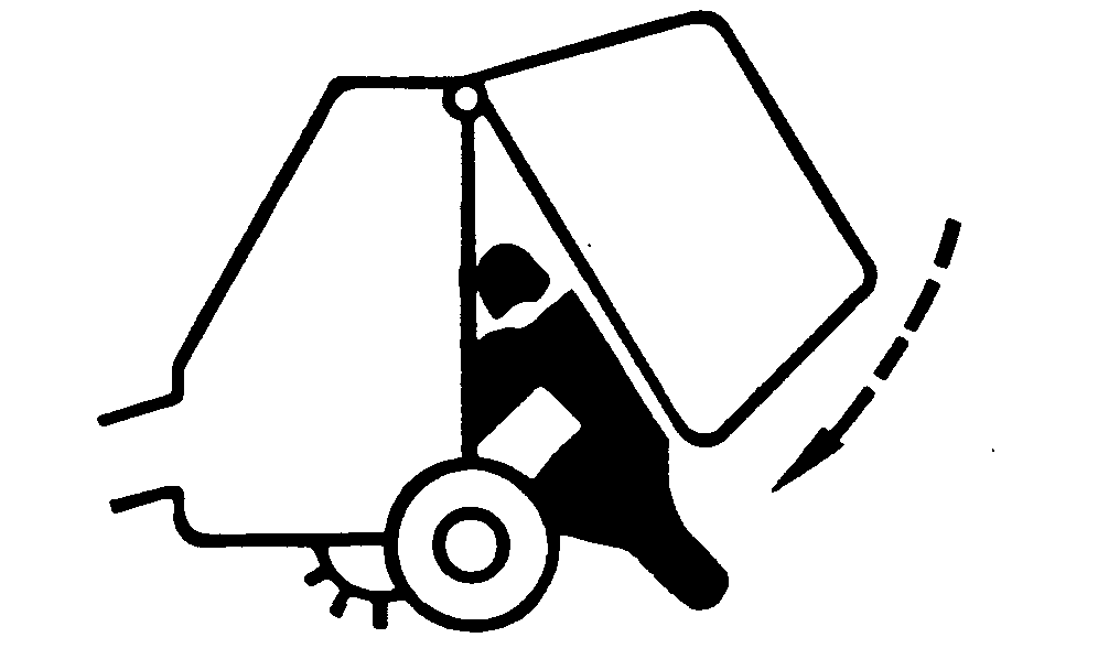
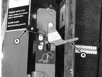
 CAUTION:
While working inside or around the baler with an open gate, the tension arm must be fully raised and against its stops and gate lock lever must be moved to locked position (A). Use this safety feature anytime the gate is open. Close the gate anytime the baler must be left unattended.
