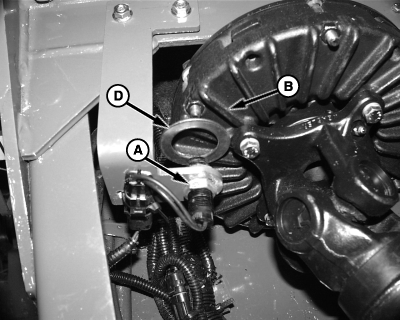
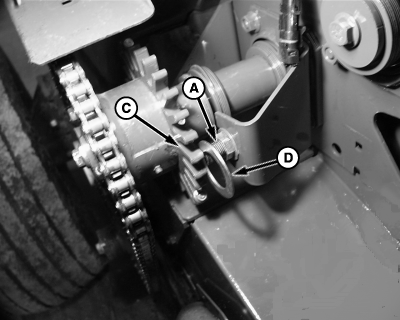
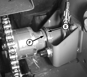
PTO and Pickup Speed Sensor AdjustmentClearance between sensor (A) and main clutch fins (B), or wheel (C) mounted to pickup clutch should be 1.6 mm (1/16 in.). A washer (D) or drill bit of this thickness can be useful in adjusting this setting. Since end play of the starter roll and slip clutch attachment on the starter roll influence sensor clearance, if possible, install additional washers at locations (E and F) to minimize looseness. Excessive looseness can result in variable gap during operation, which can cause sensor damage due to contact with the tone wheel (C) or false slip alarms due to excessive clearance. It may be helpful to tap the left end of the starter roll to force all looseness to right side of baler. Use speed readout to verify operation and adjustment of sensors. Speed of the PTO that monitor is reading, can be observed by accessing channel 16. Speed of pickup drive can be observed on channel 17. To check sensor output, use the following procedure and with tractor engine operating smoothly at low idle, observe speed readout for stability. If this readout fluctuates by more than 5 rpm, check sensor for damage or readjust sensor to reduce its clearance. Verify Operation and Adjustment of Sensors 1.
Start tractor, operate at low smooth rpm and engage PTO.
|
|
OUO6085,0000190 -19-10NOV03-1/2 |
|
6.
Release COUNTER key and pickup drive speed is displayed. This speed should be stable and not vary by more than 5 rpm.
When tractor is operated at rated PTO speed (either 540 or 1000 RPM), channel 16 should display approximately this speed and channel 17 should display approximately 310 RPM. Slip Clutch Alert System must be activated within the monitor for proper operation. (See Turning Optional Features On and OFF in this section.) If there is a problem with the slip clutch alert feature, it can be turned off by the following procedure:
|
OUO6085,0000190 -19-10NOV03-2/2 |


