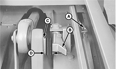
Adjusting Crank StopNOTE: Needle-to-plungerhead timing must be correct before adjusting crank stop. (See TIMING THE BALER in this section). 1. With needles in home position, adjust control rod yoke (A) so clearance (D), between right-hand point of stop (B) and lug (C) on plungerhead crank, is within specifications. Specification
2. Trip needles and turn flywheel counterclockwise until needles have raised and are on the down stroke. |
|
OUO6038,000008A -19-28SEP00-1/2 |
|
3.
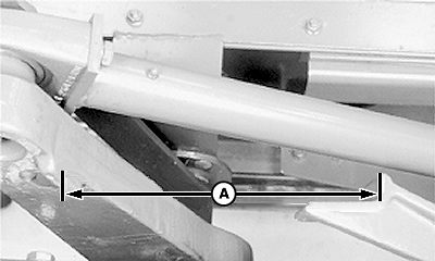
When stop starts to make its return swing to the left, clearance (A), between plungerhead crank lug and stop, must be more than specification.
Specification
4. Repeat Steps 1-3 to recheck clearance (A). |
|
OUO6038,000008A -19-28SEP00-2/2 |

