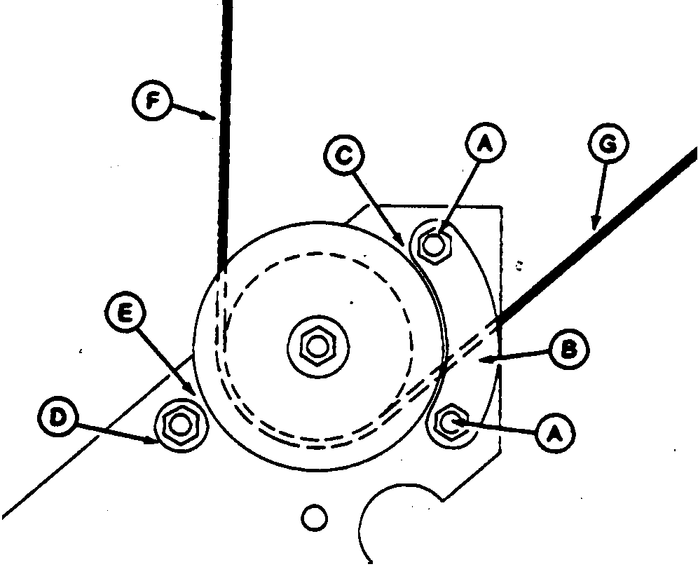
Adjusting Wire GuidesIMPORTANT: All rollers must spin freely to insure proper operation of wire twister. 1. Loosen cap screws (A) and adjust clearance (C) between front pulley and cast wire guide (B) per specification.Specification
2. Loosen cap screw and adjust clearance (E) between front sleeve guide (D) and pulley per specification. Each pulley must spin freely. Specification
|
|
OUO6038,0000098 -19-28SEP00-1/3 |
|
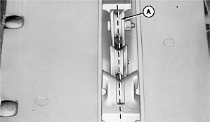
3.
With baler threaded, adjust center pulley (A) to the side, as necessary, to allow needle to pick up the wire as the needles raise.
|
|
OUO6038,0000098 -19-28SEP00-2/3 |
|
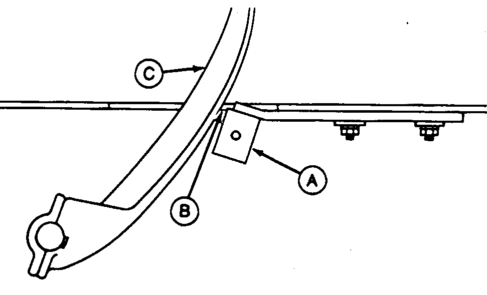
4.
With needle (C) in highest position, center pulley (A) must have a maximum clearance (B), forward of closest point of needle, as specified.
Specification
5. Adjust guides by loosening two mounting bolts in each guide. 6. Shift guides to left or right for alignment and forward or rearward for desired clearance. 7. Tighten mounting cap screws. |
|
OUO6038,0000098 -19-28SEP00-3/3 |