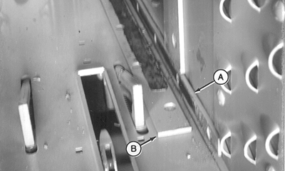
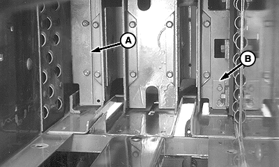
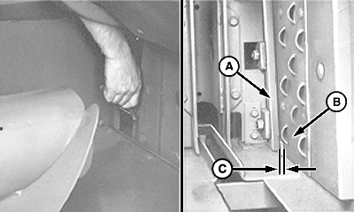
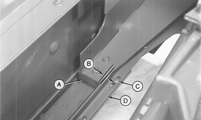
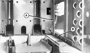
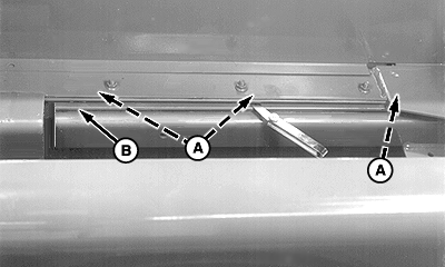
Adjusting PlungerheadIMPORTANT: Incorrect adjustment of plungerhead and/or stationary knife can cause knives to lock or shear cap screw to break. Before adjusting plungerhead, make sure stationary knife is adjusted to specification. (See ADJUSTING STATIONARY KNIFE in this section.) To prevent binding of plungerhead, make sure scrapers are loosened before adjusting plungerhead. 1. Rotate flywheel to move plungerhead to front of baler. Inspect lower right bale case side guide (A) and bottom right bale case guide (B) for wear. Replace if worn. 2. Shim lower right bale case side guide (A) until the wear surface is straight within 0.76 mm (0.030 in.) along entire length of guide. |
|
OUO6078,0005323 -19-20NOV06-1/18 |
|
3.
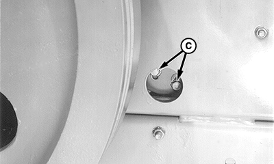
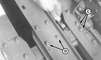
Loosen rear scrapers (A and B). Loosen cap screws (C) to loosen front scraper.
|
|
OUO6078,0005323 -19-20NOV06-2/18 |
|
4.
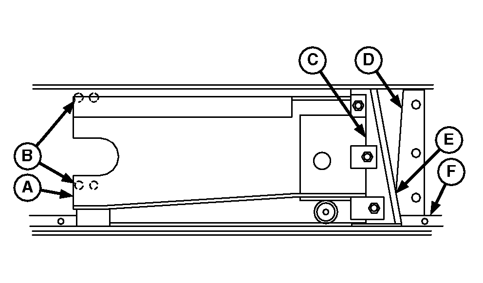
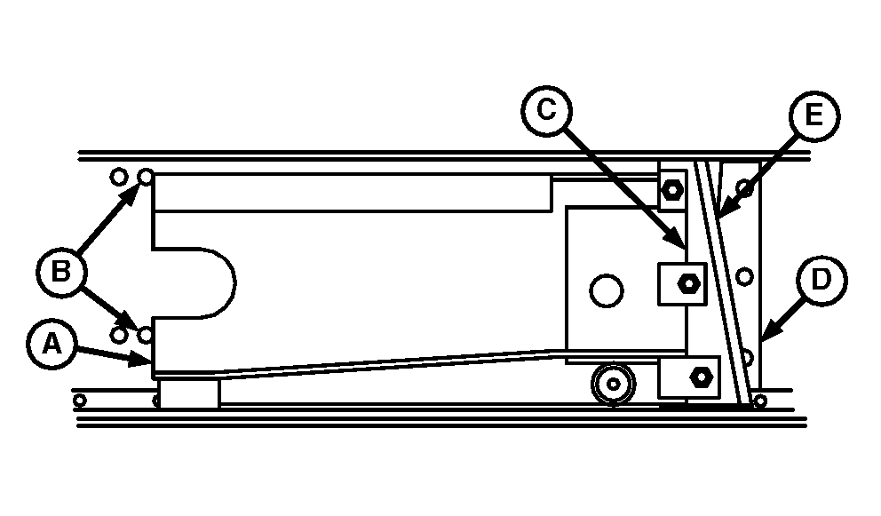
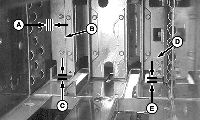
Rotate flywheel until front edge (A) of plungerhead is aligned with front edge of round-head bolt head (B). Scissor point (E) of plungerhead knife (C) and stationary knife (D) will be at "bottom position" as illustrated.
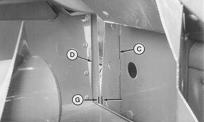
5. Push and hold plungerhead to right side of bale case against the lower right side bale case guide plate (F). 6. Check clearance (G) between plungerhead knife and stationary knife. Clearance must be within specification. Specification
|
|
OUO6078,0005323 -19-20NOV06-3/18 |
|
7.
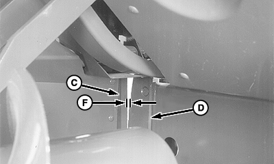
Rotate flywheel until front edge (A) of plungerhead is aligned with rear edge of round-head bolt head (B). Scissor point (E) of plungerhead knife (C) and stationary knife (D) will be at "top position" as shown in drawing.
NOTE: Scissor point of knives is shown lower in the photo for illustration purposes only. 8. Check clearance (F) between plungerhead knife and stationary knife. Clearance must be within specifications. Specification
|
|
OUO6078,0005323 -19-20NOV06-4/18 |
|
9.
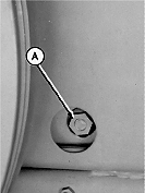
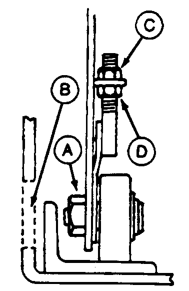
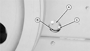
If knife clearance at top scissor position is not within specification, rotate flywheel until left rear plungerhead roller aligns with access hole in left side of bale case.
10. Loosen locking nut (A), then:
11. Recheck knife clearance at top scissor position. If clearance is within specification, tighten all roller nuts. 12. Rotate flywheel until plungerhead is at rearmost position. 13. Push and hold plungerhead to the left against the left bale case angle guide. |
|
OUO6078,0005323 -19-20NOV06-5/18 |
|
14.
Check for clearance (C) between plungerhead knife (A) and lower right side guide plate (B). Clearance must be within specification. If not within specification, adjust left angle guide.
Specification
|
|
OUO6078,0005323 -19-20NOV06-6/18 |
|
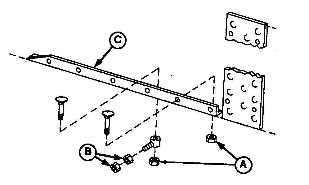
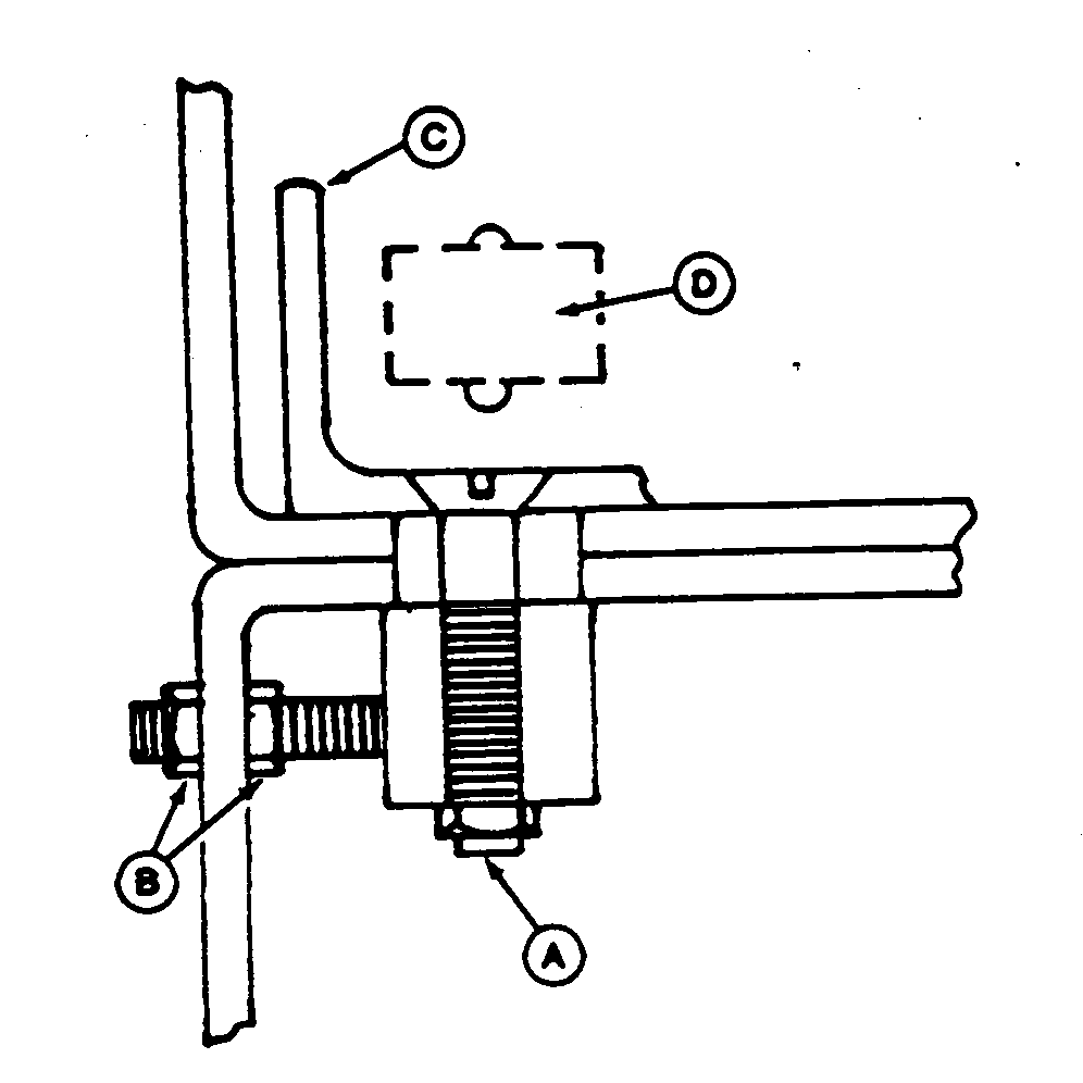
IMPORTANT: Incorrect adjustment can cause knives to lock or shear cap screw to break. Do not use anchor cap screw and nuts (B) to move lower left angle guide (C). Anchor cap screw and guide can bind and become distorted. Only use the anchor cap screw and nuts to hold clearance after guide adjustment has been made. NOTE: A total of six plow cap screw are used to fasten the lower left angle guide (C). Three of the plow cap screw and nuts (A) are used with anchor cap screw. The other three plow cap screw, washers, and nuts (A) fasten directly to the bale case and machine frame. 15. To adjust left angle guide, loosen six nuts (A) and six anchor nuts (B). 16. Pry plungerhead to extreme right side of bale case. 17. Move lower left angle guide (C) towards right until guide contacts plungerhead side roller (D). 18. Snug rearmost anchor nuts (B) and rearmost plow bolt nut (A). Do not tighten the other anchor nuts and plow cap screw at this time.
|
|
OUO6078,0005323 -19-20NOV06-7/18 |
|
IMPORTANT: To prevent plungerhead knocking, this adjustment should be as tight as possible without binding. 19. With plungerhead in the rearmost position, check for clearance (B) between lower right plungerhead wear pad (A) and angle guide (D). Clearance must be within specification and plungerhead must not bind. Specification
20. To adjust clearance, loosen five round-head cap screw (C) and move angle guide until proper clearance is achieved. 21. Snug rearmost round-head bolt (C). Do not tighten the other angle guide round-head cap screw at this time. 22. Move plungerhead to the forward position of the stoke and check for clearance (B) again. Adjust front angle guide (D) as necessary, then tighten all round-head cap screw (C). Plungerhead must move freely without binding for entire stroke. |
|
OUO6078,0005323 -19-20NOV06-8/18 |
|
23.
With plungerhead in forward position of the stroke, push plungerhead to the left against left bale case angle guide. Clearance between plungerhead knife (A) and right side guide plate (B) must not exceed specification.
Specification
|
|
OUO6078,0005323 -19-20NOV06-9/18 |
|
24.
Push left angle guide (C) tight against plungerhead side roller. Tighten all anchor bolt nuts (B), then check clearance between plungerhead knife and right side guide plate again.
25. If clearance within specification and plungerhead does not bind, tighten all plow bolt nuts (A).
|
|
OUO6078,0005323 -19-20NOV06-10/18 |
|
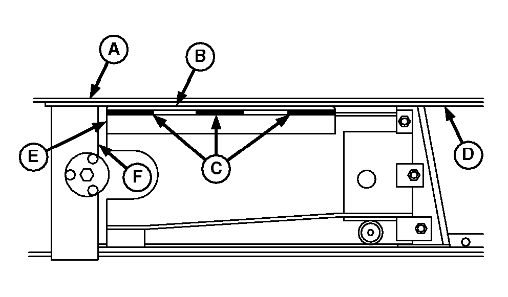
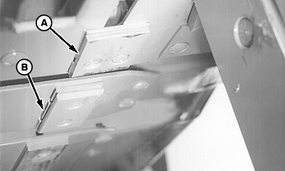
IMPORTANT: Make sure knife clearance and plungerhead side movement is within specification before adjusting the plungerhead wear plates and bale case guide extension plates. 26. Move plungerhead forward until front edge of plungerhead (E) aligns approximately with rear edge of bracket (F). IMPORTANT: The upper right plungerhead wear plate clearance must not exceed specification or plungerhead knock may occur. Make sure plungerhead does not bind as plungerhead is moved through complete cycle. A plungerhead that binds may cause shear cap screw to break. NOTE: It is recommended that the upper right plungerhead wear plate clearance be initially set at approximately 0.8 mm (0.030 in.). The clearance may be set tighter, but keep in mind that the tighter the clearance, the more chance the plungerhead may bind at some point in plungerhead stroke. 27. Check clearance between upper right plungerhead wear plate (B) and upper right bale case guide plate (D). Measurement should be taken in the location of each of the three shim packs (C). Clearance at each location should be within specification. Specification
|
|
OUO6078,0005323 -19-20NOV06-11/18 |
|
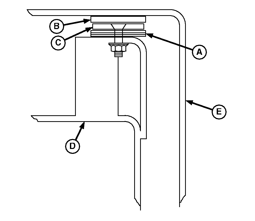
IMPORTANT: It is not necessary to have the same amount of shims in the three shim pack locations (A), but there MUST NOT be more shims in the center shim pack than at the end shim packs. NOTE: Shim packs (A) insert between the plungerhead frame and plungerhead upper right wear plate (B). 28. If clearance not within specification, loosen plungerhead upper right wear plate (B) plow cap screw. Add or remove shims as necessary at shim pack locations (A), then tighten plow cap screw. Keep the same clearance throughout entire length of plungerhead upper right wear plate. |
|
OUO6078,0005323 -19-20NOV06-12/18 |
|
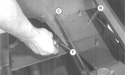
IMPORTANT: Incorrect adjustment of plungerhead wear plates may cause plungerhead knock (too much clearance) or may cause plungerhead to bind in bale case (too little clearance) causing shear cap screw to break. When plungerhead is in the forward position, clearance between plungerhead upper left wear plate and bale case upper left guide plate should not exceed 1.5 mm (0.060 in.) at the closest point between wear plate and guide plate. NOTE: It is recommended that the plungerhead upper left wear plate clearance be initially set at approximately 0.8 mm (0.030 in.). The clearance may be set tighter, but keep in mind that the tighter the clearance, the more chance the plungerhead may bind at some point in plungerhead stroke. Measurement must be taken at the closest point between wear plate and guide plate. 29. With plungerhead at the forward position as described in Step 26, check clearance between plungerhead upper left wear plate (C) and bale case upper left guide plate (B) using a feeler gauge (F). Clearance must be within specification and plungerhead must not bind. Specification
30. Loosen the two plungerhead wear plate nuts to add or remove slotted shims (A) as necessary. |
|
OUO6078,0005323 -19-20NOV06-13/18 |
|
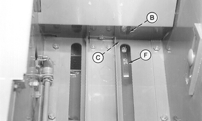
IMPORTANT: Incorrect adjustment of plungerhead wear plates may cause plungerhead knock (too much clearance) or may cause plungerhead to bind in bale case (too little clearance) causing shear cap screw to break. When plungerhead is at the "top scissor position", clearance between plungerhead upper left wear plate and bale case upper left guide plate should not exceed 1.5 mm (0.030 in.) at the closest point between wear plate and guide plate 31. Move plungerhead rearward until knives are at the "top scissor position" as described in Step 7. Check clearance between plungerhead upper left wear plate (C) and bale case upper left guide plate (B) using a feeler gauge (F). Clearance must be within specification and plungerhead must not bind. Specification
32. If clearance exceeds specification or plungerhead binds, repeat Steps 29-31 until clearance for plungerhead upper left wear plate is within specification when plungerhead is at both the "top scissor position" and "forward position". Plungerhead must not bind at any time. |
|
OUO6078,0005323 -19-20NOV06-14/18 |
|
|
|
|
|
|
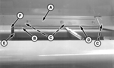
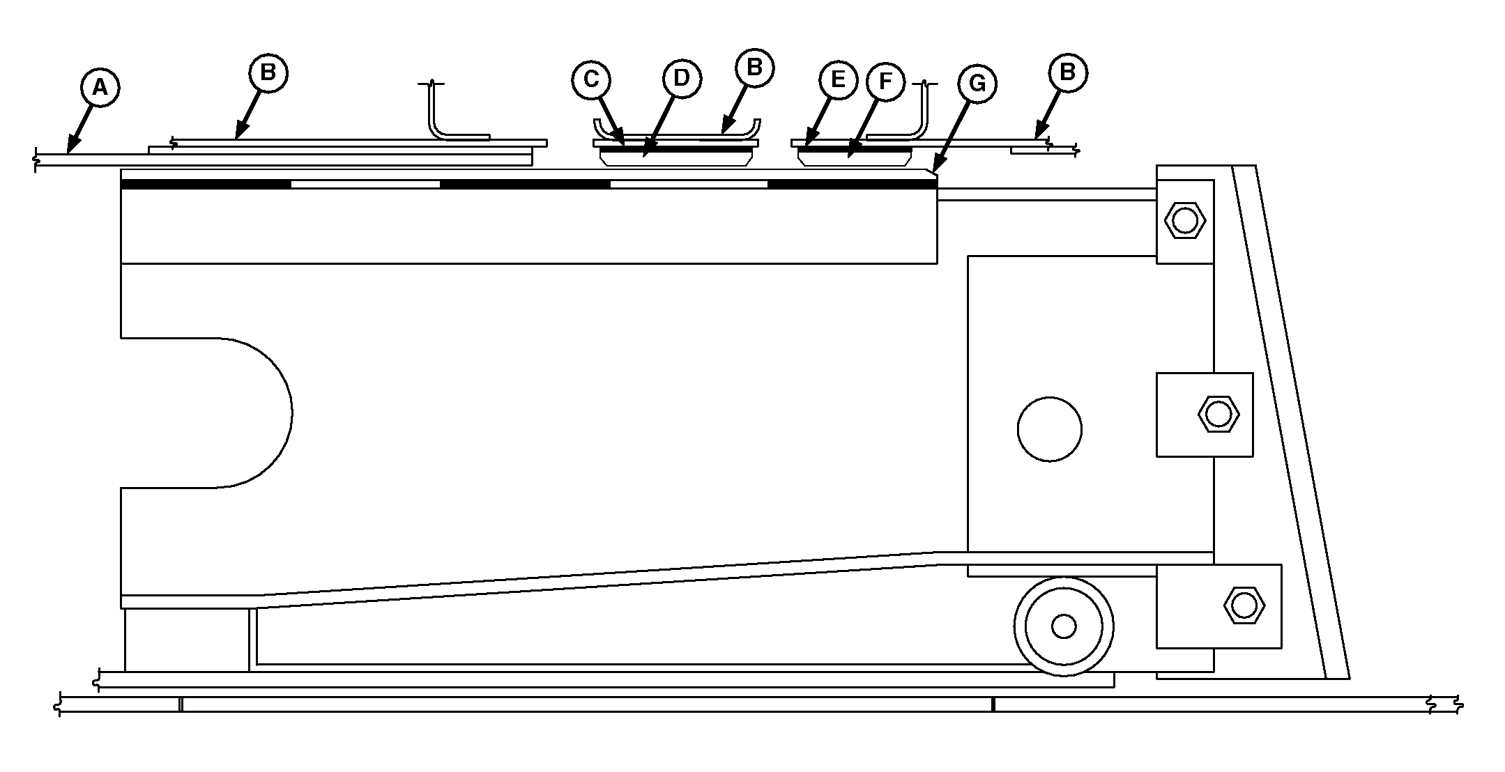
IMPORTANT: Incorrect adjustment of bale case upper right guide extension plates (D and F) may cause plungerhead knock (too much clearance) or may cause plungerhead to bind in bale case (too little clearance) causing shear cap screw to break. When plungerhead is at the "top scissor position", clearance between plungerhead upper right wear plate and bale case upper right guide extension plates should not exceed 1.5 mm (0.030 in.). |
33. With plungerhead at the "top scissor position", check clearance between plungerhead upper right wear plate (G) and bale case upper right guide extension plates (D and F). Clearance must be within specification at the closest point between wear plate and guide plates without plungerhead binding. Specification
|
OUO6078,0005323 -19-20NOV06-15/18 |
|
34.
Loosen nuts (D) to add or remove slotted shims (B).
35. Loosen nuts (C) to add or remove slotted shims (A).
|
|
OUO6078,0005323 -19-20NOV06-16/18 |
|
IMPORTANT: Scrapers must not lift plungerhead rollers off bale case guide plates. 36. Adjust left rear scraper (B):
Specification
NOTE: It is recommended the scraper clearance be adjusted closer to lower specification. Specification
37. Adjust right rear scraper (D). Scraper-to-bale case lower right guide plate clearance (E) should be within specification. Specification
|
|
OUO6078,0005323 -19-20NOV06-17/18 |
|
38.
Move plungerhead until front scraper cap screws (C) are visible in left bale case access hole. Check scraper-to-bale case left angle guide clearance. Clearance should be within specification.
Specification
39. After plungerhead adjustments are complete, move plungerhead by hand through one complete cycle. Plungerhead must move easily without binding throughout the complete plungerhead cycle. 40. If plungerhead binds, identify the problem, then make the necessary adjustment(s). IMPORTANT: Keep in mind that adjusting one area may affect another. |
|
OUO6078,0005323 -19-20NOV06-18/18 |
