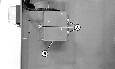
Adjusting Bale Shape Senders1. Put a board approximately 51 x 102 x 457 mm (2 x 4 x 18 in.) between roller bearing and belt as shown. 2. Position board to hold bale shape sender arm so rear of roller bearing is 55 mm (2-11/64 in.) (A) from rear edge of panel (B). 3. Later Model; Remove lock nut, round-head bolt and rotate tail/warning light shield away from baler
|
|

AG,OUMX005,1375 -19-19MAR00-1/3 |
|
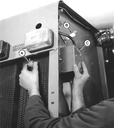
4. Loosen nuts (A) of shield (B).
|
|
AG,OUMX005,1375 -19-19MAR00-2/3 |
|
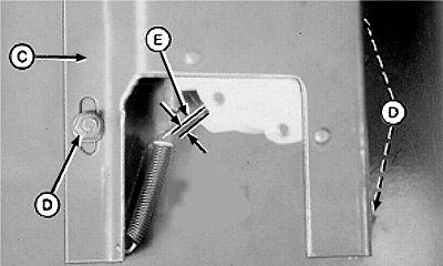
NOTE: Shield (C) has been cut away for illustration purpose only. 5. With roller (A) in 55 mm (2-11/64 in.), move shield (C) up or down so that sending unit arm (E) just touches bottom stop. 6. Tighten shield nuts (D). 7. Repeat Steps 1 through 6 on opposite side. 8. Later Model; Rotate shield toward baler and fasten with round-head bolt and lock nut. If needles do not reach top "dot" in indicators, check bale shape sender and/or replace indicators. (See your John Deere dealer.)
|
|
AG,OUMX005,1375 -19-19MAR00-3/3 |