Detaching Platform
IMPORTANT: To prevent machine damage and insure a properly operating platform, it is necessary to read this manual and the 890 Platform manual to familiarize yourself with the operation of the John Deere 4890 Self-Propelled Windrower and 890 Platform. 1. Start windrower. |
|
AG,OUO6038,1094 -19-08OCT99-1/12 |
|
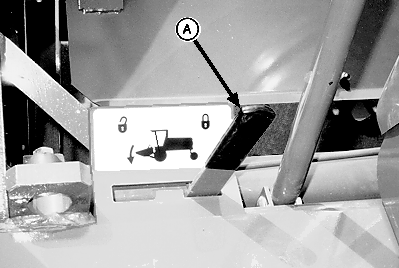
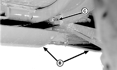
2. Raise platform and engage platform transport lock (A). Shut off windrower. 3. Raise all gauge shoes (B) to lowest cutting height and remove cotter pins (C) from right-hand and left-hand lift arm retaining pins. 4. Start windrower, disengage transport lock, lower platform to the ground and shut off windrower.
|
|
AG,OUO6038,1094 -19-08OCT99-2/12 |
|
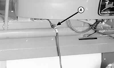
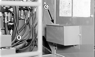
5. Disconnect electrical wiring harness (A) from windrower. 6. Turn knob (B) on accumulator/float pressure valve counterclockwise to release pressure in the accumulator. NOTE: Components removed should be placed in the storage box (C). 7. Components needed may be found in the storage box (C).
|
|
AG,OUO6038,1094 -19-08OCT99-3/12 |
|
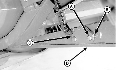
NOTE: Do not remove roll opener assembly from the platform or the bracket (C) from the chain. 8. Remove both cap screws (A), spacers (B) and bracket (C) from lower lift arm on both sides.
|
|
AG,OUO6038,1094 -19-08OCT99-4/12 |
|
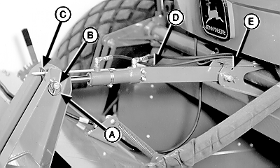
9. Start windrower and bump platform tilt switch on hydrostatic drive control until the upper link (D) moves without any movement in the platform. Shut off windrower. 10. Remove spring pin (A), pin (B) and guard angle indicator (C). Move upper link assembly (D) upward. NOTE: Bolt in the hole (E) will hold the upper link assembly up and out of the way. 11. Remove 10x120 mm bolt from the storage box and position in hole (E). 12. Install spring pin (A), pin (B) and guard angle indicator (C) back on the platform for safe keeping. |
|
AG,OUO6038,1094 -19-08OCT99-5/12 |
|
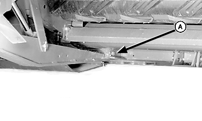
IMPORTANT: Note the quantity and location of washers, on pivot pins (A), used to position the lift arms in the platform. NOTE: It may be necessary to gently rock the platform to release any pressure on pivot pins (A) or place jack under each end of knockdown bar. 13. Remove pivot pins (A) and washers from both sides of platform. IMPORTANT: With engine running check float pressure. If float pressure does not read zero, repeat STEP 6 in this procedure. NOTE: When backing the unit, watch the hydraulic hoses connected to the hydraulic motor on the platform. The hydraulic hoses are the same length so the 16 ft. and 18 ft. platforms can not move back as far as the 14 ft. platform. 14. Start windrower, lower lift arms and backup windrower the distances listed below, for different platform lengths, from the platform. Shut off windrower.
15. Install pivot pins (A), washers and cotter pins, removed in Step 13, back on platform for safe keeping. |
|
AG,OUO6038,1094 -19-08OCT99-6/12 |
|
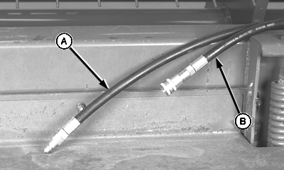
16. If equipped, disconnect hydraulic reel drive hoses (A and B).
|
|
AG,OUO6038,1094 -19-08OCT99-7/12 |
|
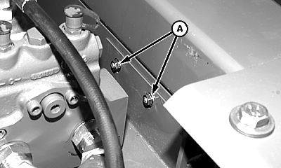
17. Remove two round-head bolts and flange nuts (A). 18. Lower conditioner drive shield.
|
|
AG,OUO6038,1094 -19-08OCT99-8/12 |
|
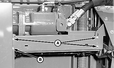
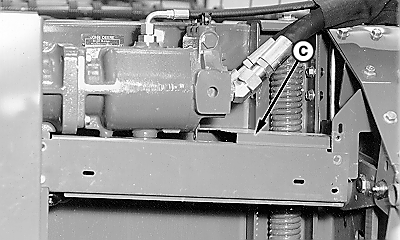
19. Remove flange head cap screws (A) and loosen flange head cap screw (B). 20. Pivot shield (C) downward enough for hydraulic motor to clear top of shield.
|
|
AG,OUO6038,1094 -19-08OCT99-9/12 |
|
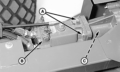
21. Remove two upper cap screws (A) and two lower cap screws holding the motor in position.
22. Move hydraulic motor horizontally away from the gear case, disengaging the splined coupler, allowing it to rest on the ground. 23. Remove splined coupler (C), connecting motor shaft and gearbox shaft, and store in the storage box provided. |
|
AG,OUO6038,1094 -19-08OCT99-10/12 |
|
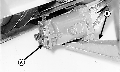
IMPORTANT: Do not allow hydraulic motor to drop when moving windrower. Windrower is not designed to be transported without the platform attached. To do so may cause rear axle damage and possible loss of steering control. 24. If moving the windrower a short distance on a smooth surface, position hydraulic motor (A) on the left front lift arm (B) and hold motor in position with a piece of wire. |
|
AG,OUO6038,1094 -19-08OCT99-11/12 |
|
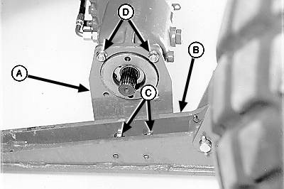
25. If moving the windrower a long distance on an uneven surface:
|
|
AG,OUO6038,1094 -19-08OCT99-12/12 |
 CAUTION:
To prevent bodily injury it is necessary to read this manual and the 890 Platform manual to familiarize yourself with the operation of the John Deere 4890 Self-Propelled Windrower and 890 Platform.
