Preparing for the Field1. Seat is adjusted and comfortable. (See Operator's Station section.) 2. Steering column tilt and height are adjusted and in a comfortable position, (See Operator's Station section.) 3. Set windrower swath flaps for desired windrow width. (See ADJUSTING SWATH FLAPS in this section.) 4. Set caster wheel width as needed. (See ADJUSTING CASTER WHEEL WIDTH in the Wheels, Steering, Brakes, and Rear Axle section.) |
AG,OUO6038,1097 -19-08OCT99-1/3 |
|
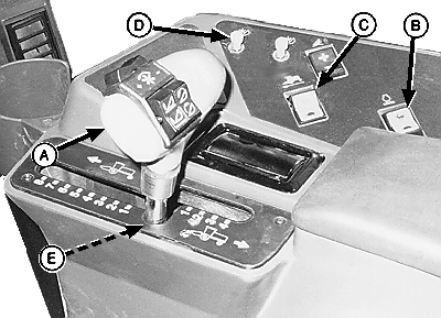
IMPORTANT: When the hydrostatic drive control lever and steering are locked out, to prevent damage to the linkage and mechanism, do not try to move them or apply any force against them. NOTE: The hydrostatic ground drive lever must be at rest to the left in the neutral position. This will engage the neutral switch (E), allowing the unit to start.
When the unit is running, the steering wheel is locked and the parking brake is applied when the hydrostatic drive lever is at rest in the neutral position. When the unit is running, moving the hydrostatic drive control lever to the right, still in neutral position, will release the steering and brakes. Turning the steering wheel at this time will cause the windrower to pivot (spin turn) between the drive wheels. Moving the drive lever forward while turning, will increase the turning radius. 5. See PARKING WINDROWER in this section. 6. Start the engine. (See STARTING THE ENGINE in Operating the Engine section.) 7. Raise and lockout the platform. (See RAISING AND LOWERING PLATFORM in this section.) 8. See 890 Platform Operator's Manual for setting reel speed. 9. Set platform gauge shoe height. (See 890 Platform Operator's Manual for adjusting gauge shoe height.) |
|
AG,OUO6038,1097 -19-08OCT99-2/3 |
|
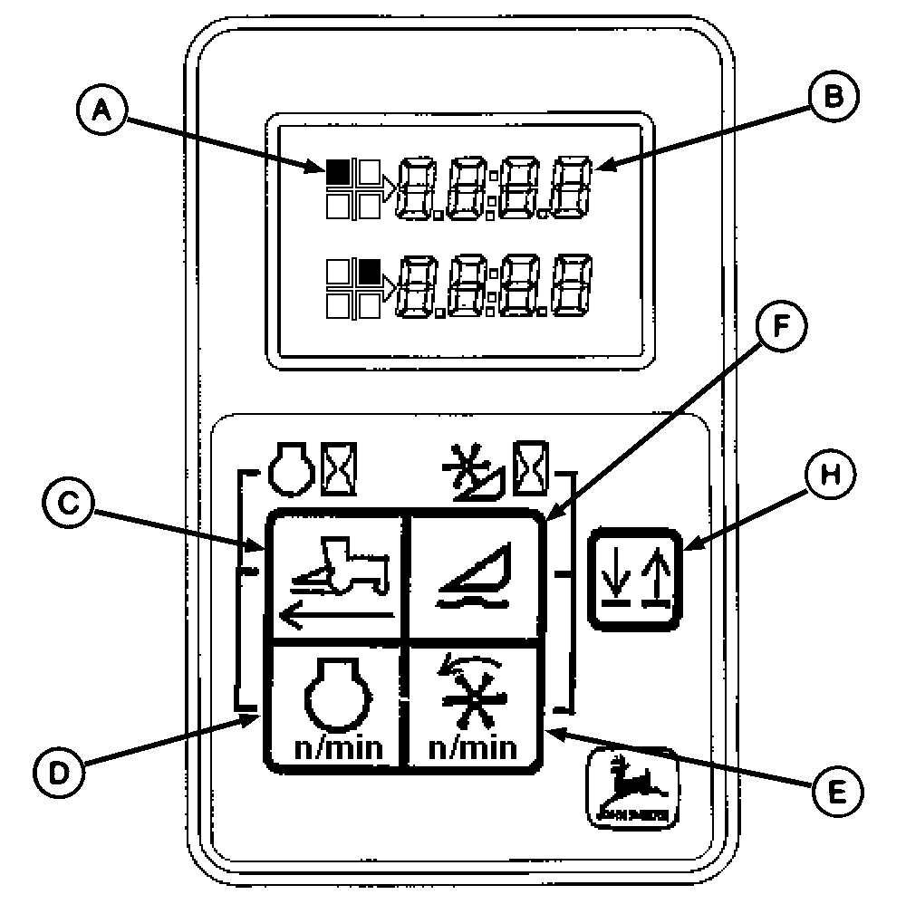
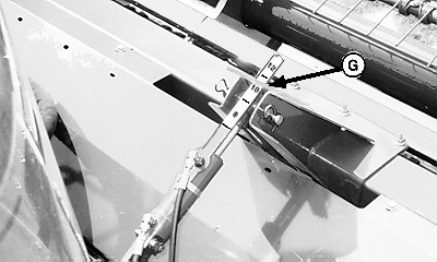
10. Press display selector (H) positioning display indicator arrow on upper (B) or lower display. 11. Press symbol of function (C), (D) or (F) to be displayed, function display (A) will move to indicate the function being shown in the upper (B) or lower display. 12. Press display selector (H) positioning display indicator arrow on other display. 13. Press another symbol of function (C), (D) or (F) to be displayed. See OPERATING THE DUAL DIGITAL DISPLAY in Operator's Station section. NOTE: When setting platform float pressure (F) and the platform guard angle (G), the engine speed (D) should be at idle speed. 14. Check platform float pressure and platform guard angle. If the settings need to be adjusted, see ADJUSTING PLATFORM FLOAT and ADJUSTING PLATFORM GUARD ANGLE in this section. NOTE: Steering is accomplished by turning the wheel right or left, except when backing. Steering is reversed when backing the machine. Place hand on bottom half of steering wheel and rotate in direction of desired turn. 15. Move hydrostatic drive lever forward for forward travel and rearward for reverse travel. |
|
AG,OUO6038,1097 -19-08OCT99-3/3 |


