Adjusting Caster Wheel Width
|
1. Park windrower on level ground. Lower platform and stop engine. |
2. Block caster wheel on opposite side being adjusted. |
AG,OUO6038,1098 -19-08OCT99-1/3 |

|
|
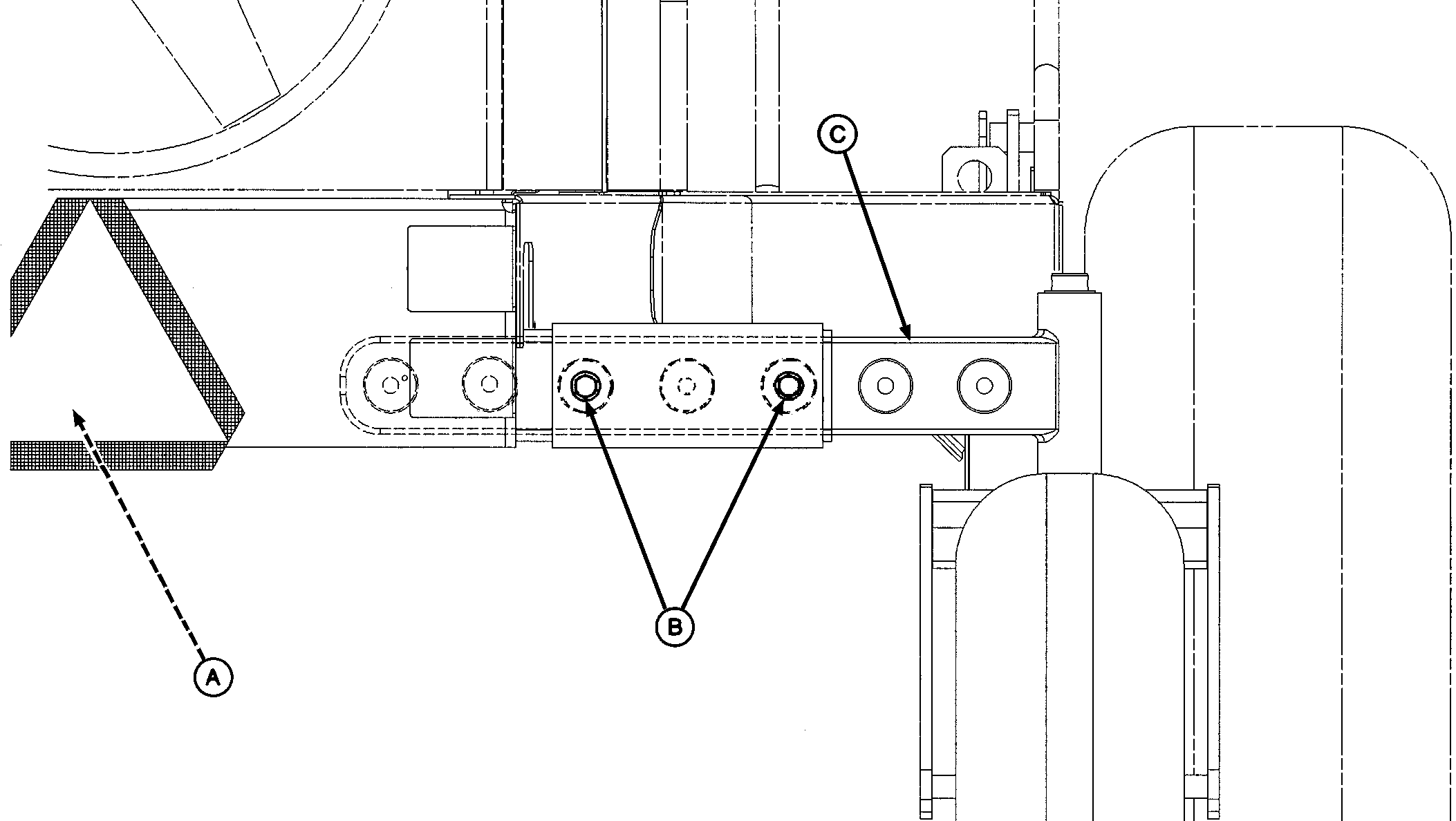
NOTE: Rear axle pivots at location (A). Lift at end of the center axle, not at axle knee (C). If using a hoist, do not block access to cap screws, washers, spacers and flange nuts (B). 3. With a hydraulic floor jack or an overhead hoist, lift rear axle at one side. Install jack stand.
|
4. Remove cap screws, washers, spacers, and flange nuts (B). NOTE: Recommended axle width shown, using third and fifth holes, unless laying down a full width swath. Both axle knees must be adjusted to the same distance from the center pivot. 5. Slide axle knee (C) in or out of center axle until desired width is obtained. |
AG,OUO6038,1098 -19-08OCT99-2/3 |
|
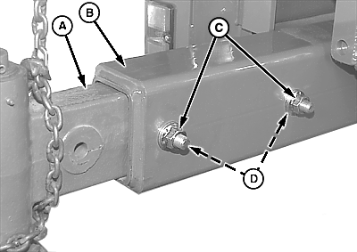
IMPORTANT: Spacers (D) will fit through larger holes in axle (B) up against axle knee (A). When assembled, the axle knee (A) will be pushed to the rear of axle (B). Assemble both cap screws through inner axle. Do not extend axle beyond desired limits. Maximum axle width is 3.5 m (11 ft 4 in.) and minimum width is 2.1 m (6 ft 10 in.). 6. Install cap screws, washers, spacers (D), and flange nuts (C) and tighten to specifications. Specification
7. Repeat Steps 2-6 on the opposite side. |
|
AG,OUO6038,1098 -19-08OCT99-3/3 |
 CAUTION:
Lift only one side at a time.
