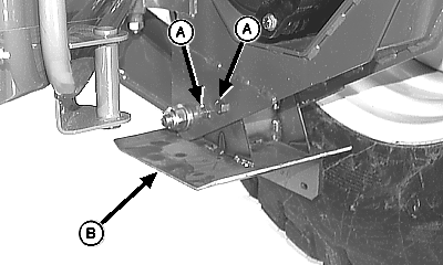
Assemble Windrower1. Remove cap screws (A) and nuts. 2. Remove shipping skid (B). 3. Repeat Steps 1 and 2 on opposite side.
|
|
AG,OUO6038,1218 -19-11OCT99-1/5 |
|
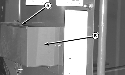
4. Components (A) required to assemble the 4890 Self-Propelled Windrower are located inside the left-hand compartment door (B).
|
|
AG,OUO6038,1218 -19-11OCT99-2/5 |
|
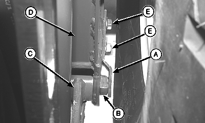
5. Install retaining bracket (A) on the outside of wheel drop (D), covering head of cap screw (B). NOTE: Lock nuts will be to the inside of the wheel drop. 6. Install two cap screws (E) through bracket (A) and wheel drop (D), and fasten with lock nuts. 7. Repeat Steps 5 and 6 on opposite side.
|
|
AG,OUO6038,1218 -19-11OCT99-3/5 |
|
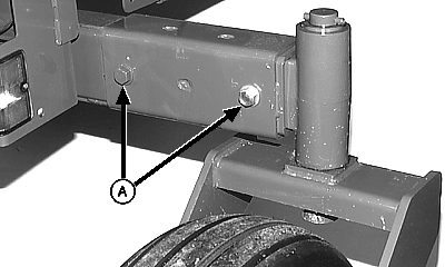
IMPORTANT: Tighten axle tube cap screws (A) to 675 N·m (500 lb-ft) 8. Adjust rear caster wheels to desired tread width. (See ADJUSTING CASTER WHEEL WIDTH in the Wheels, Steering, Brakes, and Rear Axle section.)
|
|
AG,OUO6038,1218 -19-11OCT99-4/5 |
|
9. Check torque on front wheel nuts and rear wheel cap screws. Specification
10. Check tire pressure on front and rear wheels. Specification
11. Check fluid levels:
|
|
AG,OUO6038,1218 -19-11OCT99-5/5 |
