Additional Functions for Electronic Selective Control Valves
Page for selective control valves (SCVs)
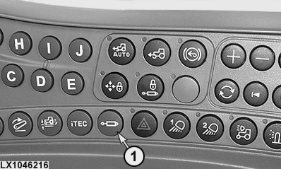
LX1046216-UN-22JUN11
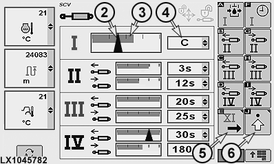
LX1045782-UN-20JAN11
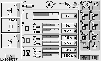
SCV Page I to IV
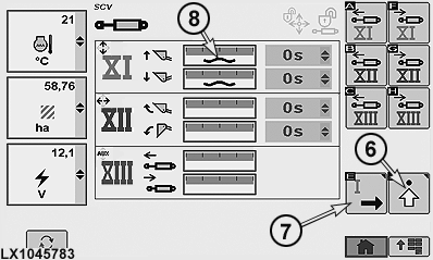
LX1045783-UN-19JAN11
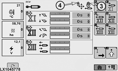
SCV Page XI to XIII
1 - Button, SCVs
2 - Rate of Flow Arrow
3 - Display Bar, Maximum Rate of Flow
4 - Drop Down Box, Shut-Off Time
5 - Softkey, SCV Page XI to XIII
6 - Advanced Settings Softkey
7 - Softkey, SCV Page I to IV
8 - Float Position Icon
Press SCV button (1) to access the SCV page.
Each SCV can be set to and operated in two different modes:
-
Default mode, see SCV I.
In default mode, rate of flow and shut-off time for extending and retracting are set and used together.
-
Independent operating mode, see SCV
II
In independent mode, rate of flow and shut-off time for extending and retracting are set and used separately.
SCVs I to IV are located at the rear and their current status is displayed on SCV page I to IV.
Display bar (3) indicates the preset maximum flow rate of the SCV. Arrow (2) represents the actual rate of flow.
Shut-off time can be read at drop-down box (4).
SCVs XI to XIII are located below the right access step. SCV page XI to XIII can be accessed using softkey (5).
 CAUTION: Danger of accidents!
Do not operate front loaders in conjunction with intelligent Total Equipment Control (iTEC™).
IMPORTANT: Before operating a front loader, make sure that the front-loader mode has been activated for SCVs XI and XII. See Set Front Implement or Front Loader Mode on the following pages.
If an SCV is operating in float position, float position icon (8) appears on the SCV page at the relevant SCV.
NOTE: Float position is not available for SCVs XII and XIII.
Determine the operating modes of Selective Control Valves
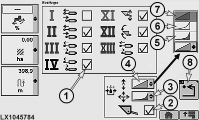
LX1045784-UN-21JAN11
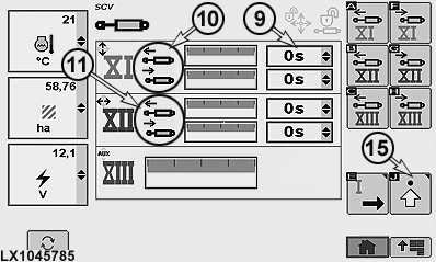
LX1045785-UN-21JAN11
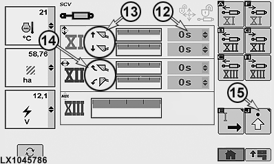
LX1045786-UN-21JAN11
1 - Choice Box, Default or Independent Operating Mode
2 - Choice Box, Front Loader or Front Implement Mode
3 - Drop-Down Box, Response of SCVs XI to XIII
4 - Drop-Down Box, Response of SCVs I to IV
5 - Progressive Response
6 - Combination Response
7 - Linear Response
8 - Previous Page Softkey
9 - Drop-Down Box, Shut-Off Time Deactivated
10 - SCV XI in Front Implement Mode, Extend/Retract
11 - SCV XII Extend/Retract
12 - Drop-Down Box, Shut-Off Time Activated
13 - SCV XI in Front Loader Mode, Raise/Lower
14 - SCV XII in Front Loader Mode, Tilt Back/Dump
15 - Advanced Settings Softkey
The following operating modes can be set for all SCVs:
- Default Mode
- Independent Operating Mode
- Front-Loader or Front-Implement Mode (SCVs XI and XII only)
- Response of Selective Control Valves
To determine the various operating modes of the SCVs, access the SCV page and press softkey (15) to access the advanced settings page.
Determine default mode or independent operating mode for SCVs
Select the required SCV and activate or deactivate choice box (1) for independent operating mode.
-
Default mode — Choice box (1) deactivated
Display bar changes, see SCV XIII.
-
Independent operating mode — Choice box (1) activated
Display bar changes, see SCV XI and XII.
Determine front-implement or front-loader mode
CAUTION: Danger of accidents!
Do not operate front loaders in conjunction with intelligent Total Equipment Control (iTEC™).
IMPORTANT: Before operating a front loader, make sure that the front-loader mode has been activated for SCVs XI and XII.
NOTE: When front-loader mode is deactivated, a warning signal can be heard five times. SCV shut-off times are set to zero.
Activate or deactivate choice box (2) for front-loader mode.
-
Front-implement mode — Choice box (2) deactivated
Function displays (10) and (11) on SCV page XI to XIII change to extend and retract.
Drop-down boxes (9) for shut-off times are active and can be set individually.
-
Front-loader mode — Choice box (2) activated
Function display (13) on SCV page XI to XIII changes to raise and lower.
Function display (14) on SCV page XI to XIII changes to tilt back and dump.
Drop-down boxes (12) for shut-off times are set to zero and are inactive.
Determine response of Selective Control Valves
SCV response can be set using drop-down boxes (3) or (4).
- Linear (7) means that the flow rate of the SCV corresponds to the distance travelled by the control lever / multi-function lever
- Progressive (5) means that initially the flow rate of the SCV is less than that travelled by the control lever / multi-function lever (giving a more sensitive start to the movement)
- Combination (6) is an intermediate stage between the two settings described above
Determine the settings of Selective Control Valves
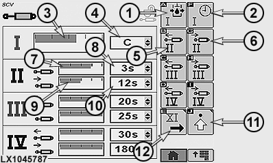
LX1045787-UN-20JAN11
SCV Page I to IV
1 - Softkey, Maximum Rate of Flow at SCV I
2 - Softkey, Shut-Off Time at SCV I
3 - Display Bar, Maximum Flow at SCV I
4 - Drop-Down Box, Shut-Off Time at SCV I
5 - Softkey, Maximum Rate of Flow at SCV II, Extend
6 - Softkey, Maximum Rate of Flow at SCV II, Retract
7 - Display Bar, Maximum Flow at SCV II, Extend
8 - Drop-Down Box, Shut-Off Time at SCV II, Extend
9 - Display Bar, Maximum Flow at SCV II, Retract
10 - Drop-Down Box, Shut-Off Time at SCV II, Retract
11 - Advanced Settings Softkey
12 - Softkey, SCV Page XI to XIII
To determine the settings for the individual SCVs, access SCV page I to IV or XI to XIII.
- Default mode, see SCV I.
- Independent operating mode, see SCV II.
The following values can be set for the SCVs:
- Maximum flow
- Automatic shut-off time
NOTE: The values for maximum flow can be set in increments of 0.04. The minimum is 0.2, and the maximum 10.
NOTE: Possible settings are a continuous flow C or an automatic shut-off time in increments varying between 0 and 180 seconds.
If flow is continuous, no automatic shut-off is possible.
ACOUSTIC WARNING SIGNAL (for tractors in North America only):
In operating modes “maximum through-flow” and “automatic shut-off”, a continuous warning signal can be heard for approx. 5 seconds if the operator vacates his seat while the reverser lever is in position P or N.
Default mode - Determine the settings
To determine the maximum flow rate, either select softkey (1) or select display bar (3) and determine the maximum rate of flow.
To determine the automatic shut-off time of the SCV I, either select softkey (2) or drop-down box (4) and determine the desired shut-off time.
Independent mode - Determine the settings
In independent mode, the settings for rate of flow and automatic shut-off must be set individually for each extend and retract function of the SCV.
To determine the maximum flow rate of the extend function, either select softkey (5) or select display bar (7) and determine the maximum rate of flow.
To determine the maximum flow rate of the retract function, either select softkey (6) or select display bar (9) and determine the maximum rate of flow.
To determine the shut-off time of the extend function, select drop-down box (8) (or drop-down box (10) for the retract function) and determine the desired shut-off time.
Automatic shut-off
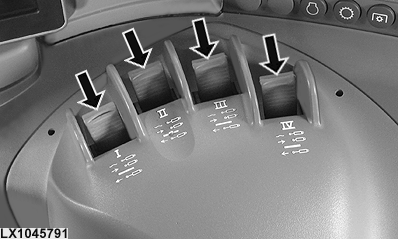
LX1045791-UN-21DEC10
If the transport lock is not active and a shut-off time greater than zero is set for the SCV, the following applies:
If the SCV control lever (see arrow) is in the maximum extend or retract position and then moved past the point of resistance (a definite click can be perceived), the relevant SCV will be brought to its maximum throughflow position and held there until the set shut-off time elapses. Then the control valve is moved to its neutral position.
This procedure is aborted if:
- the SCV control lever is not returned to its neutral position within one second
- the SCV control lever is moved out of its neutral position before the shut-off period has elapsed
- the SCV control lever is moved in the opposite direction
In all above-mentioned cases, the SCV will react according to the movements of the SCV control lever.
To re-activate the automatic shut-off, move the control lever out of neutral once again and move it to the click position.
NOTE: ACOUSTIC WARNING SIGNAL (for tractors in North America only):
In operating modes “maximum through-flow” and “automatic shut-off”, a continuous warning signal can be heard for approx. 5 seconds if the operator vacates his seat while the reverser lever is in position P or N.
Transport lock
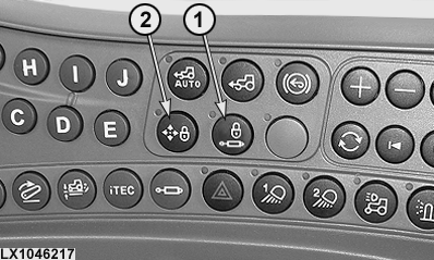
LX1046217-UN-22JUN11
LX1045777-UN-20JAN11
SCV Page I to IV
LX1045778-UN-19JAN11
SCV Page XI to XIII
1 - Button for Transport Lock, SCVs I to IV
2 - Button for Transport Lock, SCVs XI to XIII
3 - Lock Icon, SCVs I to IV
4 - Lock Icon, SCVs XI to XIII
Button (1) can be used to activate transport lock for all SCVs I to IV and XI to XIII simultaneously. All the selective control valves go to neutral. This appears on the SCV page as lock icons (3) and (4).
The indicator lights next to buttons (1) and (2) light up when transport lock is activated.
Pressing button (1) again deactivates SCVs I to IV. The indicator light on the button goes out and the relevant lock icon (3) appears gray or goes out.
Pressing button (2) again deactivates SCVs XI to XIII. The indicator light on the button goes out and the relevant lock icon (4) appears gray or goes out.
The transport lock of SCVs XI to XIII can be activated without locking SCVs I to IV.
IMPORTANT: Activate transport lock buttons (1) and (2) when driving on roads and whenever the control levers are in neutral because they are not required.
|
OULXA64,00026C7-19-20120619 |