Replacing Right-Hand End Disk Driver
-
Raise front platform doors to access cutterbar.
-
 CAUTION: Knives have two cutting edges. Be careful when working
around the knives. Knives are sharp and can cause serious injury.
Wear gloves when handling knives.
CAUTION: Knives have two cutting edges. Be careful when working
around the knives. Knives are sharp and can cause serious injury.
Wear gloves when handling knives.
To avoid serious injury, rotate both knives on all disks, so they are positioned UNDER the disks.
TS268-UN-23AUG88 -
Put a block of wood between left-hand end disk and outer sidesheet to prevent disks from turning.
-
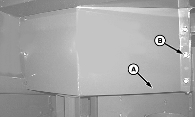
E47637-UN-10JAN00A - Shield
B - Cap Screws (6 used)
Remove six cap screws (B) and shield (A). -
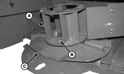
E47683-UN-21JAN00A - Converging Drum
B - Cap Screw (4 used)
C - Disk
Remove four cap screws (B), converging drum (A) and disk (C). -
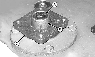
E47726-UN-28JAN00A - Cap Screw
B - Special Washer
C - Disk Driver
Remove cap screw (A) and special washer (B). -
Remove disk driver (C).
-
If splines have been sheared, remove loose pieces of splines.
-
IMPORTANT: It is critical that mating surfaces of the bearing, driver, and special washer be free of dirt and crop material before installing special hardened cap screw. If these areas are not thoroughly cleaned, the cap screw can come loose and cause cutterbar failure.
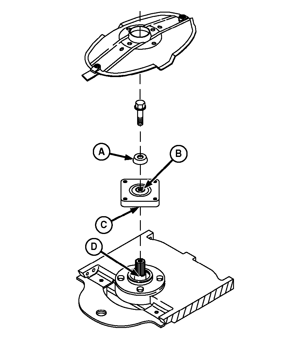
E44404-UN-02JUL98A - Special Washer
B - Top of Driver
C - Bottom of Driver
D - Top of Bearing
Clean the following areas before installing disk driver:- Special washer (A)
- Top (B) of driver
- Bottom (C) of driver
- Top of bearing (D)
-
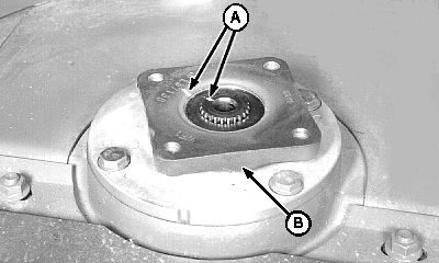
E44179-UN-24JUL97A - Timing Marks
B - Driver
Align timing marks (A) and install new driver (B) on pinion shaft. -
E47726-UN-28JAN00A - Cap Screw
B - Special Washer
C - Driver
Align timing mark on special washer (B) with mark on driver (C). Install washer. -
IMPORTANT: To avoid machine damage, use new special cap screw treated with thread-locking compound.
Replace the special hardened cap screw with genuine John Deere part specified for this application.
Lubricate cap screw with light oil before installation. Failure to lubricate could allow cap screw to come loose and cause machine damage.
Lubricate cap screw (A) with light oil.
-
Install cap screw and tighten to specification.
Item Measurement Specification Disk Driver to Pinion Gear Cap Screw Torque 340 N˙m (250 lb-ft) -
IMPORTANT: Each disk must be installed 90° to the adjacent disk (this is called synchronization). If the disks are not 90° to each other, damage to machine will result.
Disk-to-driver cap screws are treated with thread-locking compound and can be used up to five times. Replace with the John Deere cap screw specified for this application.
NOTE: Disk life can be extended by moving disk to a location of opposite rotation. If this is done, the knives must be interchanged for proper cutting direction. (See INSTALLING AND SYNCHRONIZING DISKS and INSTALLING KNIVES in this section.)
Replace cap screws after removing and installing five times.
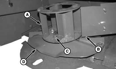
E47682-UN-24JAN00A - Converging Drum
B - Lower Crop Shield
C - Cap Screw (4 used)
D - Disk
Install disk (D) in original position (90° to adjacent disk). Align mounting holes in converging drum (A) and install four cap screws (C). Tighten according to specification.Item Measurement Specification Disk to Driver Cap Screws Torque 150 N˙m (110 lb-ft) -
Adjust clearance between lower crop shield (B) and disk (D). (See ADJUSTING LOWER CROP SHIELDS in this section.)
-
IMPORTANT: When installing converging drum shield there should be a 1—6 mm (0.04—0.24 in.) clearance between shield and converging drum.
E47637-UN-10JAN00A - Shield
B - Cap Screw (6 used)
Install shield (A). Make sure the clearance between shield and top of converging drum is according to specifications.Item Measurement Specification Shield to Converging Drum Distance 1—6 mm (0.04—0.24 in.) -
Remove wood block and rotate disks by hand to make sure disks and knives do not interfere with each other or other cutterbar components.
-
Lower front platform doors.
|
AG,OUO6040,718-19-20080925 |