Adjusting Cut Height—Turnbuckle Top Link
E48351-UN-14JUL00
E41409-UN-17FEB97
E47649-UN-13JAN00
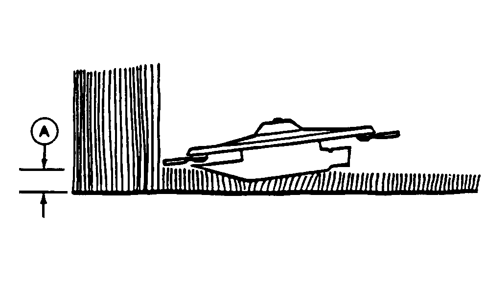
A - Cut Height
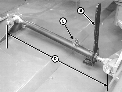
B - Special Wrench
C - Quick-Lock Pin
D - Dimension
IMPORTANT: A higher height of cut will minimize machine damage in rocky conditions.
-
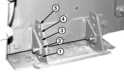
The cut height (A) is determined by the angle of cutterbar and position of gauge shoes, if installed. Select cut height from chart below and adjust gauge shoes, as necessary. (See ADJUSTING GAUGE SHOES in this section.)
-
NOTE: The information in chart is based with machine on level ground.
Minimum
Cut Height
mm (in.)
Maximum
Cut Height
mm (in.)
With Gauge Shoes
Hole 1
17 (5/8)
78 (3 1/8)
Hole 2
18 (3/4)
94 (3 3/4)
Hole 3
27 (1 1/8)
120 (4 3/4)
Hole 41
46 (1 3/4)
145 (5 3/4)
Hole 5 2
70 (2 3/4)
171 (6 3/4)
Change dimension (D) of top link to adjust cut height (A). Turning top link 2-1/2 revolutions changes cut height approximately 25 mm (1 in.).
-
For maximum cut height in each range,
set dimension (D) according to specifications.
Item Measurement Specification Maximum Cut Height Distance 657 mm (25-7/8 in.) -
For minimum cut height in each range,
set dimension (D) according to specifications.
Item Measurement Specification Minimum Cut Height Distance 784 mm (30-7/8 in.)
-
For maximum cut height in each range,
set dimension (D) according to specifications.
-
To adjust top link:
E48351-UN-14JUL00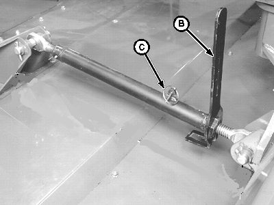
E56038-UN-25SEP08A - Cut Height
B - Special Wrench
C - Quick-Lock Pin
- Remove quick-lock pin (C) and raise special wrench (B).
- Slide wrench over adjusting nut and turn top link to obtain desired cut height (A).
- Return special wrench to original position and secure in place with quick-lock pin.
-
Adjust platform float. (See procedure in this section.)
|
1 If side gauge shoes are positioned
in holes 4 or 5, upfloat can be increased by positioning carrier frame
lift cylinders. (See ADJUSTING CARRIER FRAME HEIGHT in this section.)
|
EX,945IJ,T1-19-20080925 |