Adjusting Carrier Frame Height
Raising carrier frame height is recommended if machine is operated mainly with gauge shoes fully extended (for highest cut). Upfloat can also be increased by raising carrier frame.
IMPORTANT: Adjust top link to a length of 720 mm (28.3 in.) or less when operating machine with carrier frame in the "raised" position to prevent float spring problems. (See ADJUSTING CUT HEIGHT in this section.)
Impeller conditioner; High carrier frame position should not be used with header tipped forward. Float springs may disengage from header.
To adjust carrier frame height:
-
Put wooden blocks under each end and along center of cutterbar frame.
-
Lower machine down on blocks.
-
Shut off tractor engine.
-
 CAUTION: To avoid personal injury, support float springs before
releasing tension completely. Float springs are heavy and will swing
away from machine when disconnected.
CAUTION: To avoid personal injury, support float springs before
releasing tension completely. Float springs are heavy and will swing
away from machine when disconnected.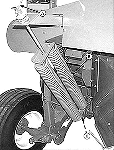
E48350-UN-11JUL00A - Crank
B - Float Spring
C - Cap Screw and Nut
Remove crank (A) from storage position and turn handle counterclockwise to release float spring tension. -
Remove cap screw and nut (C), if equipped. Disconnect float springs (B).
-
Repeat Steps 4 and 5 on opposite side.
-
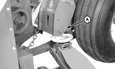
E41406-UN-08FEB97A - Carrier Frame
Install floor jack under carrier frame (A). -
Raise carrier frame to release tension from lift cylinder.
-
NOTE: Wheel is removed for illustration purpose.
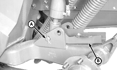
E41407-UN-08FEB97Standard Position
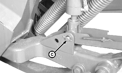
E41408-UN-08FEB97Raised Position
A - Pin
B - Lock Channel
C - Top (Rear) Hole
Remove cotter pin, pin (A), spacers and lock channel (B). -
Raise carrier frame until hole in rod end of cylinder aligns with top (rear) hole (C).
-
Install pin, lock channel and spacers. Install one washer on each side of cylinder rod between lock channel and rod. Fasten with cotter pin.
-
Lower carrier frame and remove floor jack.
-
Repeat procedure on opposite side.
-
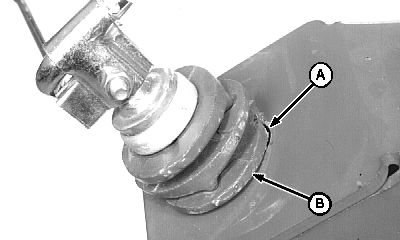
E41411-UN-08FEB97A - Inside Slot
B - Rocker Plate
Connect float springs and fasten with cap screw and nut, if equipped. Turn handle clockwise to increase float spring tension. Make sure tab on rocker plate (B) is inside slot (A) in frame. Remaining rocker plate tabs should alternate every 90 degrees and be seated in mating grooves. -
Make sure crank lubrication fitting is facing toward the outside of machine.
-
Adjust platform float. (See procedure in this section.)
|
EX,945RJ,D1-19-19990524 |