Adjusting Roll Spacing (Roll Conditioner)
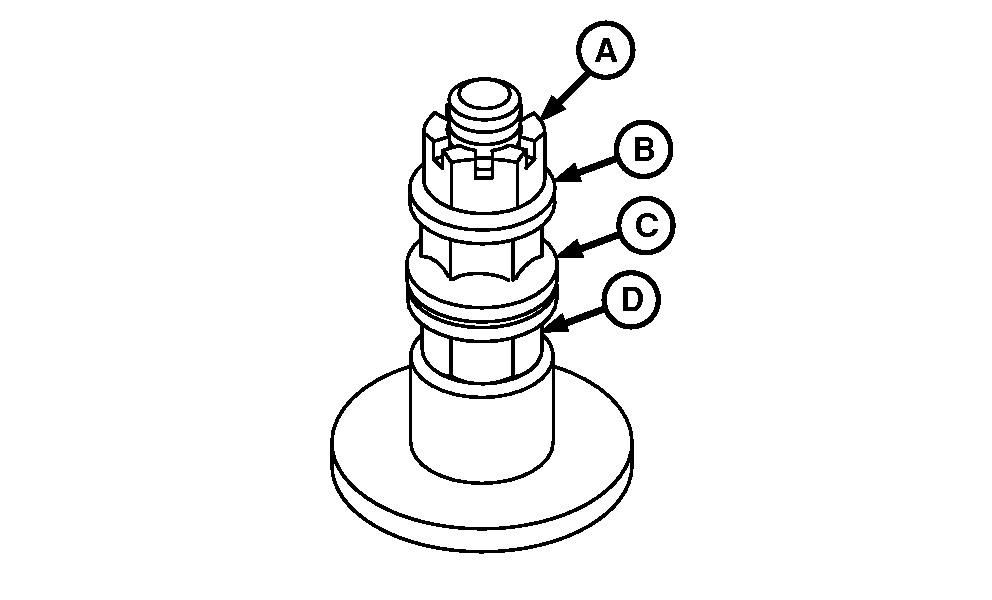
E53576-UN-04AUG04
Urethane Roll Machine Shown
A - Castellated Nut
B - Washers
C - Flange Nut
D - Flange Nut
Minimum
Roll spacing is set from factory and is maintained by a pinned castellated nut (A).
Roll spacing may be increased to reduce conditioning intensity.
- To increase roll spacing, turn nut (D) clockwise same number of turns both sides. Jam nut (C) to (D).
- To reduce roll spacing, turn nut (D) counter clockwise same number of turns on both sides. Jam nut (C) to nut (D).
- With jam nut (C), nut (D) and clamp washer (B) against castled nut (A) factory setting (minimum roll spacing) is obtained.
- See Settings for Various Crop Conditions under Operating the Mower-Conditioner section of this manual.
To compensate for normal wear or if rolls are replaced, set minimum roll spacing by the following procedure.
-
 CAUTION: To avoid bodily injury while performing this adjustment:
- Keep all shields in place.
- Keep hands and clothing away from moving parts.
- Carefully follow procedure.
IMPORTANT: Rolls should never be adjusted to allow contact during use or serious damage to machine will occur.
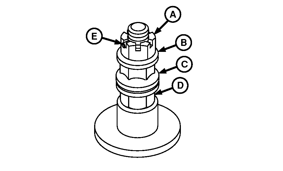
E53577-UN-04AUG04Urethane Roll Machine Shown
A - Castellated Nut
B - Washer
C - Flange Nut
D - Flange Nut
E - Roll Pin
Remove roll pin (E) from both sides. -
Loosen castellated nut (B) and flange nuts (C and D) on both sides.
-
Engage platform drive at lowest engine speed.
-
Turn flange nut (D) counterclockwise in one quarter turn increments until roll contact causes vibration and rumbling noise.
-
Turn flange nut (D) clockwise in one quarter turn increments until vibration and rumbling noise has stopped.
-
Once vibration and rumbling noise has stopped, turn nut an additional 1/2 turn clockwise.
-
Go to opposite side of platform.
-
Turn flange nut (D) counterclockwise in one quarter turn increments until roll contact causes vibration and rumbling noise.
-
Turn flange nut (D) clockwise in one quarter turn increments until vibration and rumbling noise has stopped.
-
Once vibration and rumbling noise has stopped, turn nut an additional 1/2 turn clockwise. Jam nut (C) against nut (D) by hand.
-
Go to opposite side of platform.
-
Turn flange nut (D) counterclockwise in one quarter turn increments until roll contact causes vibration and rumble noise.
-
E53577-UN-04AUG04Urethane Roll Machine Shown
A - Castellated Nut
B - Washer
C - Flange Nut
D - Flange Nut
E - Roll Pin
Turn flange nut (D) clockwise in one quarter turn increments until vibration and rumbling noise has stopped. -
Once vibration and rumbling noise has stopped, turn nut an additional 1/2 turn clockwise. Jam nut (C) against nut (D) by hand.
-
Turn off engine and remove key.
-
With flange nuts (flange to flange) and jammed together by hand, hold nut (D) and tighten nut (C) an additional 1/6-1/4 turn clockwise on both sides.
-
Install castellated nut (A) against nut (C) and washer between nuts (A and C) so at least 1/2 roll pin engages castellated nut slot. Install roll pin (E). Repeat on opposite side.
-
If hole in rod and castellated nut slot do not align, turn castled nut and flange nuts clockwise to next castellated slot. Loosen flange nuts, tighten nut (C) against castellated nut/washers, turn nut (D) to just contact nut (C), hold nut (C) and turn (D) 1/6-1/4 turn to jam nuts.
|
OUO6085,000089D-19-20080925 |