Replacing Main Drive Belt
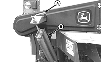
E55693-UN-25APR08
A - Crank
B - Float Springs
-
Put wooden blocks under each end of cutterbar frame.
-
Lower machine down on blocks.
-
Shut off tractor engine.
-
 CAUTION: To avoid personal injury, support float springs before
releasing tension completely. Float springs are heavy and will swing
away from machine when disconnected.
CAUTION: To avoid personal injury, support float springs before
releasing tension completely. Float springs are heavy and will swing
away from machine when disconnected.Remove crank (A) from storage position and turn handle counterclockwise to release float spring tension.
-
Remove cap screw and nut, if equipped. Disconnect float springs (B).
-
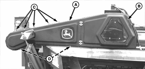
E55688-UN-25APR08A - Rear Cover
B - Door
C - Flange-Head Bolts and Nuts (5 used)
D - Flange-Head Bolts and Nuts (8 used)
Remove flange-head bolts and nuts (C) and (D). -
Open door (B).
-
Remove rear cover (A).
-
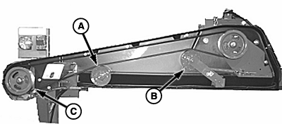
E55697-UN-25APR08A - Fixed Idler
B - Idler
C - Sheave
Loosen nuts to relieve spring tension on idler (B). -
Remove nut, washer and fixed idler sheave (A).
-
Remove driven sheave (C) if required.
-
Remove V-belt from end sheaves.
-
Install new belt in reverse order of removal.
-
If sheave (C) was removed, add LOCTITE® to bolt and retorque to within specifications
Item Measurement Specification Bolt Torque 350 N˙m 258 ft-lbs -
Install crank assembly and connect float springs. Fasten with cap screw and nut, if equipped. Install bottom of float springs in same bell crank notch location as right-hand side float springs.
NOTE: Roll machine; Check location of link in roll arm for proper location (See ADJUSTING ROLL PRESSURE in Operating the Mower Conditioner section.)
-
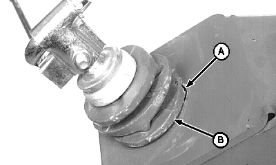
E41411-UN-08FEB97A - Slot
B - Rocker Plate
Turn handle clockwise to increase float spring tension. Make sure tab on rocker plate (B) is inside slot (A) in frame. Remaining rocker plate tabs should alternate every 90 degrees and be seated in mating grooves. -
Make sure crank lubrication fitting is facing toward the outside of machine.
-
Adjust platform float. (See procedure in Operating the Mower-Conditioner section.)
-
Adjust belt tension. (See procedure in this section.)
|
LOCTITE is a trademark of Loctite Corp. |
OUO6085,00008A7-19-20080925 |