Replacing Conditioner Drive Sheave—Roll Conditioner
If changing conditioner speed, replace sheave and belt. See your John Deere dealer.
-
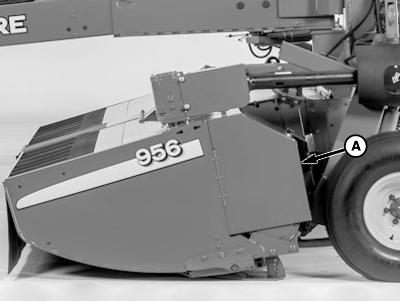
E76490-UN-14JUL14A - Door
Raise platform and engage lift cylinder stops. -
Open door (A).
-
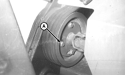
E41502-UN-16FEB97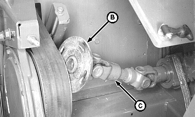
E41503-UN-16FEB97A - Cap Screw (4 used)
B - Mounting Flange
C - Yoke
Remove four cap screws (A). -
Slide yoke (C) toward machine. Turn and lift mounting flange (B) to remove from gear case driven sheave.
-
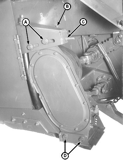
E41500-UN-16FEB97A - Cap Screws
B - Idler Adjustment Nuts
C - Draw Bolt Nut
D - Cap Screws
Loosen four cap screws (A) and (D), nuts (B) and (C). -
Push gear case forward and remove drive belt from driven sheave.
-
Remove bolt (A) and sheave. Set bolt aside.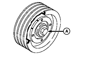
E55560-UN-28NOV07 -
Install new sheave with bolt removed earlier. Torque bolt to specification.
Item Measurement Specification Bolt Torque 340 N·m (250 lb-ft) -
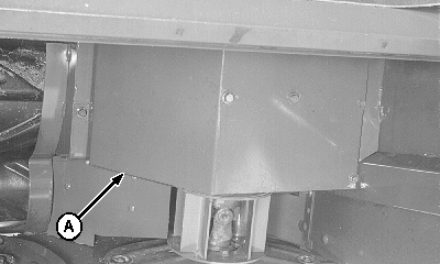
E41493-UN-15FEB97A - Shield
Raise left-hand front platform door to access drive sheave on gear case. -
Remove shield (A).
-
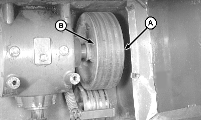
E56041-UN-25SEP08A - Belt
B - Sheave
Pull belt (A) toward front of machine and remove from sheave (B). -
Install new belt in reverse order of removal.
IMPORTANT: When installing the left-hand converging drum shield, there should be a 1—6 mm (0.04—0.24 in.) clearance between shield and converging drum.
-
Install shield. Make sure clearance between shield and top of converging drum is to specification.
Item Measurement Specification Shield-to-Converging Drum Distance 1—6 mm (0.04—0.24 in.) -
Install belt on new driven sheave. Adjust belt tension. (See ADJUSTING CONDITIONER DRIVE BELT TENSION—ROLL CONDITIONER in this section.)
-
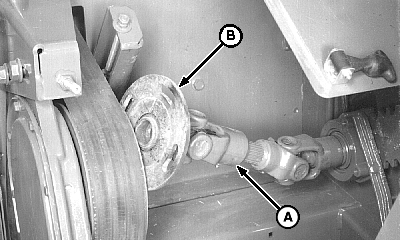
E58264-UN-24NOV09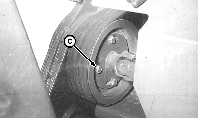
E58265-UN-24NOV09A - Yoke
B - Mounting Flange
C - Cap Screws (4 used)
Reinstall driveline: Slide yoke (A) toward sheave. Lift mounting flange (B) to install on gear case driven sheave. -
Install flange with four cap screws (C), (removed earlier). Tighten screws just snug at this time.
See ADJUSTING ROLL TIMING (ROLL CONDITIONER) in this Section.
|
PP98408,0000011-19-20140715 |