Replacing Conditioner Drive Belt—Impeller Conditioner
Practice Safe Service Procedures
TS261-UN-23AUG88
E41329-UN-27JAN97
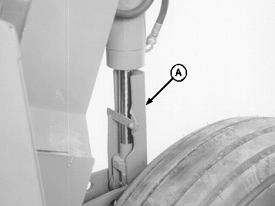
A - Cylinder Lock (2 used)
 CAUTION: To help prevent personal injury caused by unxpected
movement, be sure to service machine on a level surface.
CAUTION: To help prevent personal injury caused by unxpected
movement, be sure to service machine on a level surface.
If machine is connected to tractor, engage tractor parking brake and/or place transmission in “Park”, shut off engine and remove key.
If machine is detached from tractor, block wheels to prevent movement.
CAUTION: Engage BOTH cylinder locks when working on machine.
Failure to do so can result in personal injury or machine damage.
Before servicing or adjusting mower-conditioner:
- Disengage all power.
- Shut off tractor engine.
- Wait until all moving parts have stopped.
Before working under platform, engage both cylinder locks (A) to prevent accidental lowering of machine.
-
Raise platform and engage cylinder locks.
-
Raise left-hand side front door to access drive sheave on gear case. (See RAISING AND LOWERING FRONT DOORS AND CURTAINS in Operating the Mower-Conditioner section.)
-
E41436-UN-09FEB97946 Shown
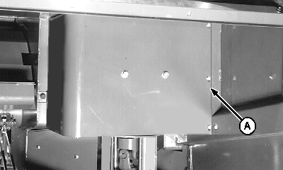
A - Shield
Remove shield (A). -
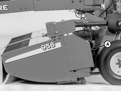
E76490-UN-14JUL14A - Door
Open door (A). -
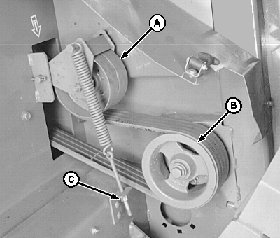
E41451-UN-10FEB97A - Idler
B - Rotor Sheave
C - Nuts and Washer
Remove two nuts and washer (C). -
Remove cotter pins, pivot pin and idler (A).
-
Remove cap screw, washer and impeller rotor sheave (B).
-
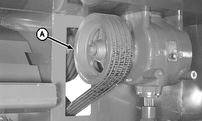
E41452-UN-10FEB97A - Sheave
Remove drive belt from sheave (A). -
Pull out belt from rear of machine.
-
Install new belt in reverse order of removal using the following special instructions:
- Tighten cap screw at impeller rotor sheave to specifications.
-
Adjust belt tension. (See procedure in this section.)
Item Measurement Specification Impeller Rotor Sheave-to-Rotor Cap Screw Torque 339 N˙m (250 lb-ft)
IMPORTANT:
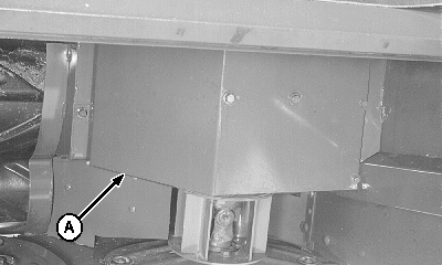
E41493-UN-15FEB97A - Shield
When installing the left-hand converging drum shield there should be a 1—6 mm (0.04—0.24 in.) clearance between shield and converging drum.Install shield (A). Make sure the clearance between shield and top of converging drum is according to specifications.
Item Measurement Specification Shield-to-Converging Drum— Distance 1—6 mm (0.04—0.24 in.)
|
PP98408,0000014-19-20140715 |