|
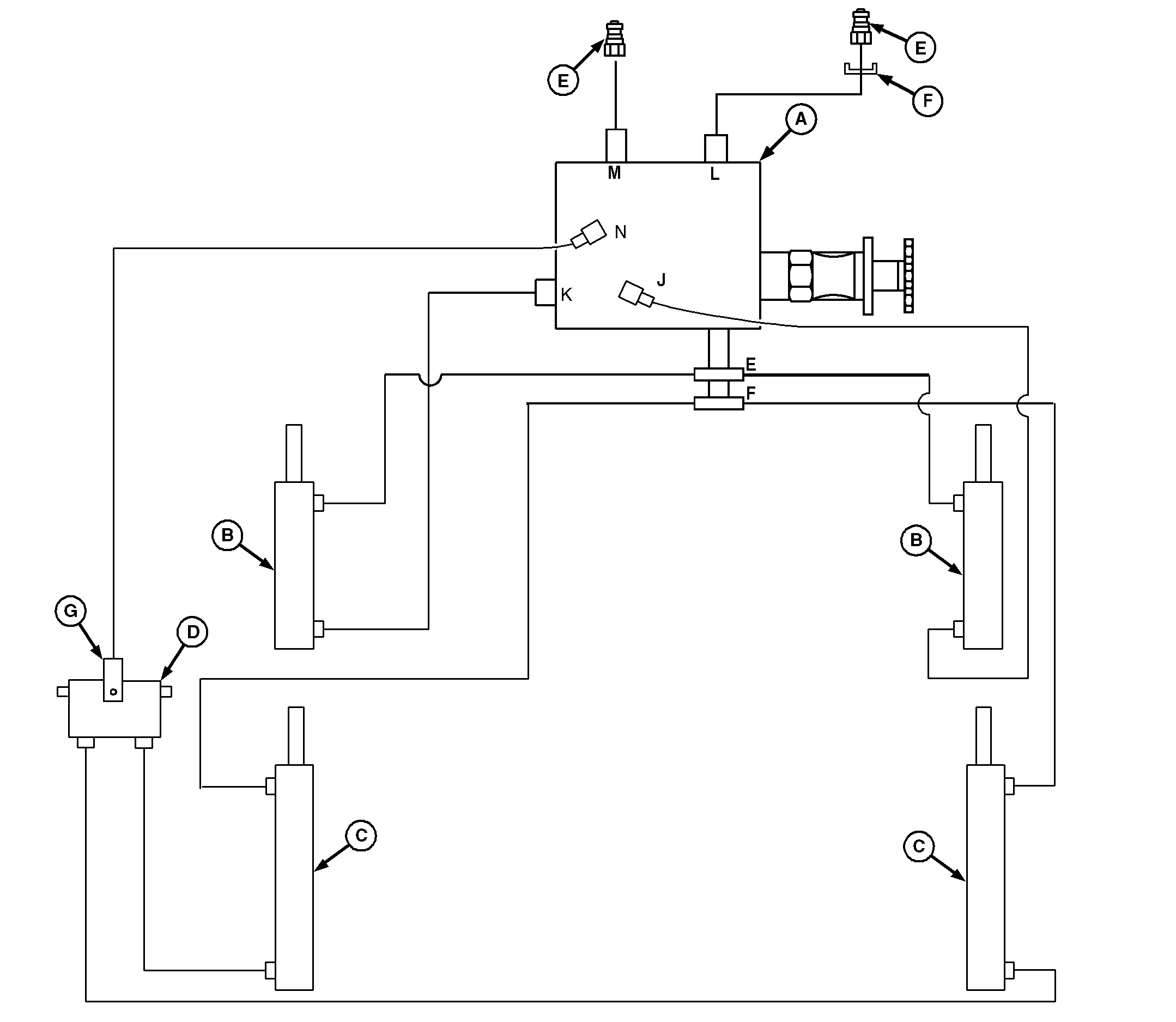
John Deere 468, 468S, and 568 Balers have a hydraulic system that controls bale tension and operates the gate. This hydraulic system is powered by the tractor.
The hydraulic system uses four major components:
-
Tensioning valve (A)-Used to direct oil flow, check flow, and limit hydraulic pressures.
|
-
Tensioning
(double-acting)
cylinders (B)-Used to control bale tensioning.
-
Gate
(double-acting)
cylinders (C)-Used to raise and lower the gate.
-
Gate lock valve (D)-A two-position spool valve used to block flow of oil, both to and from the base ports of gate cylinders (C).
-
Optional flow restrictor valve (G)-Used if baler is equipped with net wrap system and/or push bar.
|