Adjusting Pickup Float Springs-Regular Pickup (568)
|
|
|
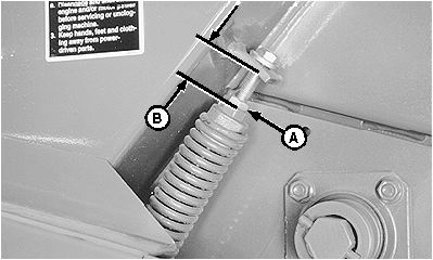
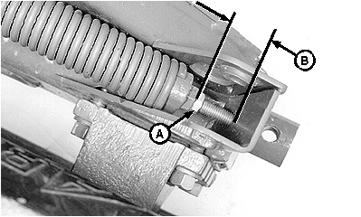
NOTE: If equipped with hydraulic pickup lift; Remove cap screw from base end of cylinder (left-hand side) to gain access for spring adjustment. Dimension (B) is an initial float spring setting for pickup tooth-to-ground clearance of 25-50 mm (1-2 in.) with wheel spindles in the normal position. (See WHEEL SPINDLE POSITIONS in Preparing the Baler section.) More spring force will be needed if:
Less spring force will be needed if:
|
1.
Loosen jam nut (A).
IMPORTANT: Any dimension less than 60 mm (2-3/8 in.) at the right-hand spring will stretch or weaken the spring. 2. Tighten screw into spring plug until dimension (B), between spring plug and spring anchor, is attained.
3. Tighten jam nut (A). |
||||||||||||||
OUO6085,00004C1 -19-19MAY06-1/1 |

