Adjust PTO and Pickup Slip Clutch Alert Sensors
(MegaWide™ Plus and MegaTooth™ Pickups)
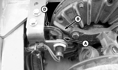
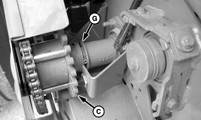
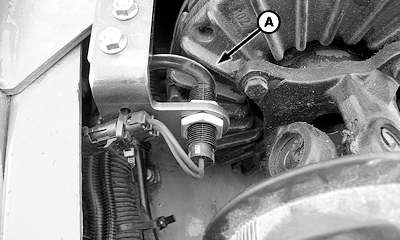
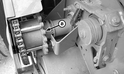
Clearance between sensor (A) and PTO clutch fins (B), or wheel (C) should be 2 ± 1 mm (0.080 ± 0.040 in.). Washer (D) or drill bit of this thickness can be useful in adjusting setting.
Adjusting Starter Roll Endplay
IMPORTANT:
Excessive starter roll endplay may cause sensor damage due to contact with wheel, or cause false slip alarms due to excessive clearance.
1.
Tap and hold starter roll shaft to left-hand side and push starter roll sprocket and washers inward.
2.
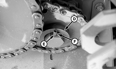
Check if additional washer(s) (D) can be added. Verify by inserting two opposing washers of the same thickness between existing washers.
3.
If needed, add thin (0.036 in.) or thicker (0.60 in.) washer(s) (D) between sprocket and spring pin (F). Position thicker washer against spring pin.
NOTE:
Install spring pin so split (E) is facing either toward sprocket or away from sprocket.
4.
Orient and install spring pin.
5.
Make sure left-hand washers (D), and/or right-hand washers (G) turn freely by hand after installing spring pin.
A-Sensor
B-PTO Clutch Fins
C-Wheel
D-Washers
E-Split
F-Spring Pin
G-Washers
|
540 RPM Bracket Assembly Shown
Right-hand Side Starter Roll
Left-hand Side Starter Roll
|
|
|
PP98408,0000089 -19-03SEP09-1/7
|
Verify Operation and Adjustment of Sensors
Use speed readout to verify operation and adjustment of sensors. Access channel 016 on monitor-controller for PTO speed and channel 017 for pickup drive speed.
1.
Start tractor and operate tractor engine at slow idle. Engage PTO.
2.
Press and hold COUNTER key while turning monitor-controller ON.
3.
Continue to hold COUNTER key and press PLUS key until
CH016
appears in digital display.
4.
Release COUNTER key and PTO speed is displayed. Speed readout should be stable and not vary by ± 5 rpm.
5.
Press and hold COUNTER key and press PLUS key until
CH017
appears in digital display.
6.
Release COUNTER key and pickup drive speed is displayed. Speed should be stable and not vary by ± 5 rpm.
7.
If speed variation exceeds ± 5 rpm, shut off tractor and remove key. Adjust appropriate sensor closer to clutch fins (A) or wheel (B), but not closer than 1 mm (0.040 in.).
When tractor is operated at rated PTO speed, channel 016 should display either 540 rpm or 1000 rpm. Channel 017 should display approximately 310 rpm. Slip clutch alert system must be activated within the monitor-controller for proper operation. (See NET WRAP, SLIP CLUTCH ALERT, and VARIABLE CORE FEATURES, TURNING ON and OFF in this section.)
Turning PTO Speed Sensor ON and OFF:
-
PTO speed sensor can be turned OFF or ON by accessing channel 204.
-
Feature can be turned ON by changing value to 540 or 1000 rpm.
-
Entire slip clutch alert feature can be turned OFF by changing value to 0.
|
540 RPM Bracket Assembly Shown
A-Clutch Fins
B-Wheel
|
|
|
PP98408,0000089 -19-03SEP09-2/7
|
|
Turning Pickup Speed Sensor ON and OFF:
-
Pickup rpm sensor can be turned OFF and ON by accessing channel 205.
-
Feature can be turned ON by changing value to 310 rpm.
-
Pickup rpm sensor can be turned OFF by changing value to 0.
-
Turning OFF the pickup sensor on channel 205 and turning ON PTO sensor on channel 204 still allows automatic speed compensation during wrapping cycle.
|
|
|
|
PP98408,0000089 -19-03SEP09-3/7
|
Adjusting PTO Sensor
NOTE:
If sensor nuts are removed, cup sides of nuts must point toward each other.
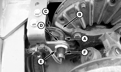
Adjust end of PTO sensor (A) 2 ± 1 mm (0.080 ± 0.040 in.) from fins (B) on PTO clutch.
NOTE:
End of sensor is a magnet. Washer/gauge may drag on magnet creating false sensor-to-fin reading during rechecks.
-
Place a 2 mm thick washer or feeler gauge (C), against end of sensor.
-
Advance sensor with washer/gauge (C) toward clutch fin (B) until gauge just makes contact.
-
Tighten nut (D) or (E) finger tight.
1.
To tighten sensor: Hold sensor at location (F) with pliers. Tighten nut (D) or (E) 2-3 flats, or 1/3-1/2 turn or 6 N·m (4.5 lb-ft).
2.
Verify sensor is not damaged after tightening nuts.
-
Connect multimeter leads to sensor connector.
-
If multimeter reads approximately 3000 Ohms, sensor is good.
-
If multimeter reads zero, sensor is bad. Replace sensor.
NOTE:
If clutch fins move more than 1 mm (0.040 in.) endplay, fore and aft, tighten bolts attaching PTO driveline to gear case. If gear case shaft is loose, see your John Deere dealer.
3.
Recheck 2 ± 1 mm (0.080 ± 0.040 in.) clearance between clutch fins and sensor while gently prying PTO clutch forward to simulate PTO driveline thrust loads.
4.
Hold PTO clutch forward and perform the following:
-
If 1 mm (0.040 in.) gauge does not pass between clutch fin and sensor, repeat Steps 1-3 to obtain proper clearance.
-
If 1 mm (0.040 in.) gauge passes between clutch fin and sensor, clearance is acceptable.
|
540 RPM Shown
A-Sensor
B-Fins
C-Washer or Feeler Gauge
D-Nut (Sensor Side of Bracket)
E-Nut (Connector Side of Bracket)
F-Location, Wire End of Sensor
|
|
|
PP98408,0000089 -19-03SEP09-4/7
|
-
If 3 mm (0.12 in.) gauge passes between clutch fin and sensor, repeat Steps 1-3 to obtain proper clearance.
|
|
|
|
PP98408,0000089 -19-03SEP09-5/7
|
Adjusting Pickup Sensor
NOTE:
Verify starter roll and wheel (B) side-to-side endplay is less than one (0.036 in.) washer. (See ADJUSTING STARTER ROLL ENDPLAY in this section.)
NOTE:
If sensor nuts are removed, cup sides of nuts must point toward each other.
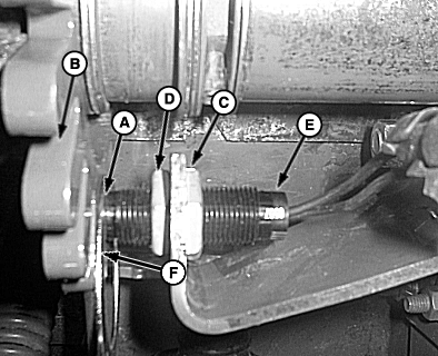
Adjust end of sensor (A) 2 ± 1 mm (0.080 ± 0.040 in.) from wheel (B).
NOTE:
End of sensor is a magnet. Washer/gauge may drag on magnet creating false sensor-to-fin reading during rechecks.
-
Place a 2 mm (0.080 in.) washer or feeler gauge (F) of this thickness against end of sensor.
-
Advance sensor with washer/gauge toward wheel until gauge just makes contact.
-
Tighten nuts (C) and (D) finger tight.
1.
To tighten sensor: Hold sensor at location (E) with pliers. Tighten nut (C) or (D) 2-3 flats, or 1/3-1/2 turn, or 6 N·m (4.5 lb-ft).
NOTE:
Check for 2 mm clearance in three locations, 120° apart. (at each wheel mounting bolt).
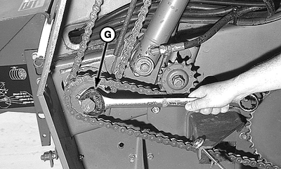
Go to left side of baler, turn output shaft using a 32 mm (1-1/4 in. wrench) (G) to turn wheel. Check for 2 ± 1 mm (0.080 ± 0.040 in.) clearance at each position. If clearance is not within specification, repeat Step 1.
Remove wrench (G) from output shaft on left side of baler.
2.
Verify sensor is not damaged after tightening nuts.
-
Connect multimeter leads to sensor connector.
-
If multimeter reads approximately 3000 Ohms, sensor is good.
-
If multimeter reads zero, sensor is bad. Replace sensor.
|
A-End of Sensor
B-Wheel
C-Nut (Electrical Connector Side)
D-Nut (Sensor Side)
E-Location (Pliers)
F-Washer or Feeler Gauge
G-Wrench, 32 mm (1-1/4 in.)
|
|
|
PP98408,0000089 -19-03SEP09-6/7
|
|
|
PP98408,0000089 -19-03SEP09-7/7
|
|
