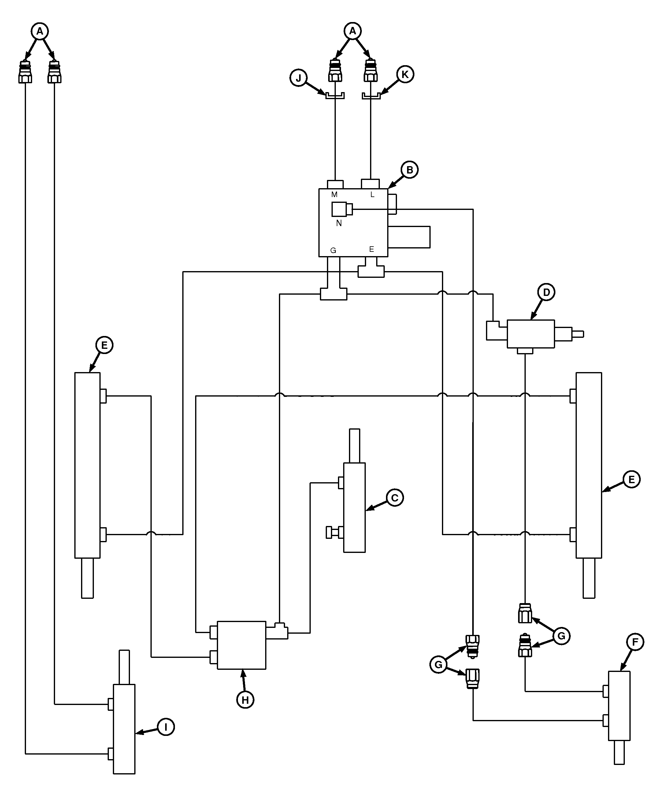
Hydraulic System Diagram
E55064-UN-19APR07
A - To Tractor SCV Ports
B - Tensioning Valve
C - Take-Up Arm Cylinder
D - Bale Ramp Regulator Valve (if equipped)
E - Tension or Gate Cylinders
F - Bale Ramp Cylinder (optional)
G - Quick-Disconnect Fittings (if equipped)
H - Gate Lock Valve
I - Pickup Lift Cylinder (if equipped)
J - Orifice (stamped 361)
K - Orifice (stamped 351)
An optional hydraulic bale ramp is available. Bale ramp is operated by bale tension or gate control system.
One set of hydraulic outlets is required to operate baler.
If baler is equipped with optional hydraulic pickup lift, an additional set of hydraulic outlets is needed.
The hydraulic system uses the following major components:
- Tensioning valve (B)—Used to direct oil flow, check flow, and limit hydraulic pressures.
- Tension or gate (double-acting) cylinders (E)—Used to raise and lower gate and to control bale tensioning.
- Take-up (single-acting) cylinder (C)—Used to provide proper sequencing between the tension arm and gate opening. Also, it helps control belt slack during gate closing to avoid belt pinching.
- Optional pickup lift (double-acting) cylinder (J)—Used to raise and lower pickup using tractor SCV.
- Optional bale ramp (double-acting) cylinder (F)—Used to automatically lower or raise bale ramp when gate is opened fully.
- Optional regulator valve (D)—Used to regulate flow to and from optional bale ramp cylinder (F) for proper sequencing of ramp and gate positions.
- Gate lock valve (H)—Used to block flow of oil to and from base ports of tension or gate cylinders (E).
|
PP98408,0000F5A-19-20130207 |