Adjust Pickup Float Springs—Regular Pickup (459 and 559)
NOTE: If equipped with hydraulic pickup lift; Remove cap screw from base end of cylinder (left-hand side) to gain access for spring adjustment.
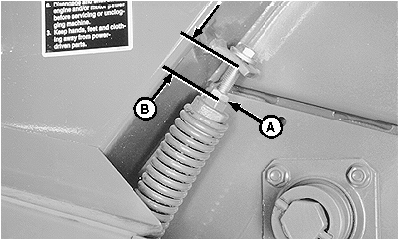
E39271-UN-19JUN96
Right-Hand Side
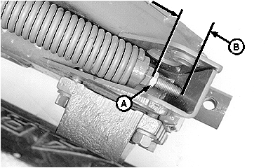
E39270-UN-19JUN96
Left-Hand Side
A - Jam Nut
B - Float Spring Setting Dimension
Dimension (B) is an initial float spring setting for pickup tooth-to-ground clearance of 25—50 mm (1—2 in.) with wheel spindles in the normal position. (See WHEEL SPINDLE POSITIONS in Preparing the Baler section.)More spring force will be needed if:
- Operating at pickup tooth-to-ground clearance above 50 mm (2 in.) with wheel spindles in the normal position.
- The baler has been lowered at the wheel spindles to improve feeding. (See BALE SHORT, DRY, SLICK CROPS in Operating the Baler section.)
Less spring force will be needed if:
- The pickup does not lower to desired operating height.
- The pickup bounces too much and leaves crop.
- The baler has been raised at the wheel spindles to improve feeding. (See BALE CORNSTALKS in Operating the Baler section.)
-
Loosen jam nut (A).
-
IMPORTANT: Any dimension less than 60 mm (2-3/8 in.) at the right-hand spring will stretch or weaken the spring.
Tighten screw into spring plug until dimension (B), between spring plug and spring anchor, is attained.
459
559
WITHOUT GAUGE WHEELS
Right-Hand Side
170 mm
(6-11/16 in.)
140 mm
(5-1/2 in.)
Left-Hand Side
155 mm
(6-3/32 in.)
140 mm
(5-1/2 in.)
WITH GAUGE WHEELS
Right-Hand Side
100 mm
(3-15/16 in.)
60 mm
(2-3/8 in.)
Left-Hand Side
100 mm
(3-15/16 in.)
10 mm
(25/64 in.)
-
Tighten jam nut (A).
|
PP98408,0000F76-19-20130207 |