Install Wheel Spindles on 459 and 559 Baler with Regular Pickup and 14L x 16.1 Tires
NOTE: Wheel spindle position controls baler height and feeding capacity.
NOTE: Normal position shown is used for most baling conditions. For other crop conditions, see WHEEL SPINDLE POSITIONS in Preparing the Baler section.
-
IMPORTANT: When raising baler with a jack or hoist, place a jackstand or equivalent support under baler frame (A) before installing spindles and tires.
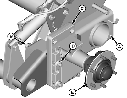
E66126-UN-22JUN12Normal Position—Optional Baler Ramp Shown
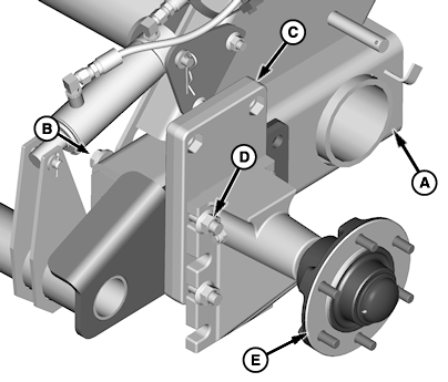
E66127-UN-22JUN12Raised Position—Optional Baler Ramp Shown
A - Location (Baler Frame)
B - Cap Screw, M16 x 180-10.9 (4 used) (Without Bale Ramp)
B - Cap Screw, M16 x 200-10.9 (4 used) (With Bale Ramp)
C - Spacer Plate
D - Flange Nut, M16 (4 used)
E - Spindle
Park baler on level surface. -
Using a jack or hoist, raise one side of baler. Place a jackstand or equivalent support under baler frame (A).
-
Install cap screws (B), spacer plate (C), flange nuts (D), and spindle (E) with offset down.
-
Tighten flange nuts to specification.
Item Measurement Specification Flange Nuts Torque 237 N·m (175 lb.-ft.) -
Repeat on opposite side.
|
PP98408,0000FD3-19-20130207 |