Set Twine Spacing
E38438-UN-19JUN96
E52444-UN-02JUN08
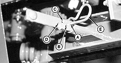
A - 5 cm (2 in.) Twine Arm Spacing
B - 10 cm (4 in.) Twine Arm Spacing
C - 15 cm (6 in.) Twine Arm Spacing
D - 20 cm (8 in.) Twine Arm Spacing
E - Spring Pin
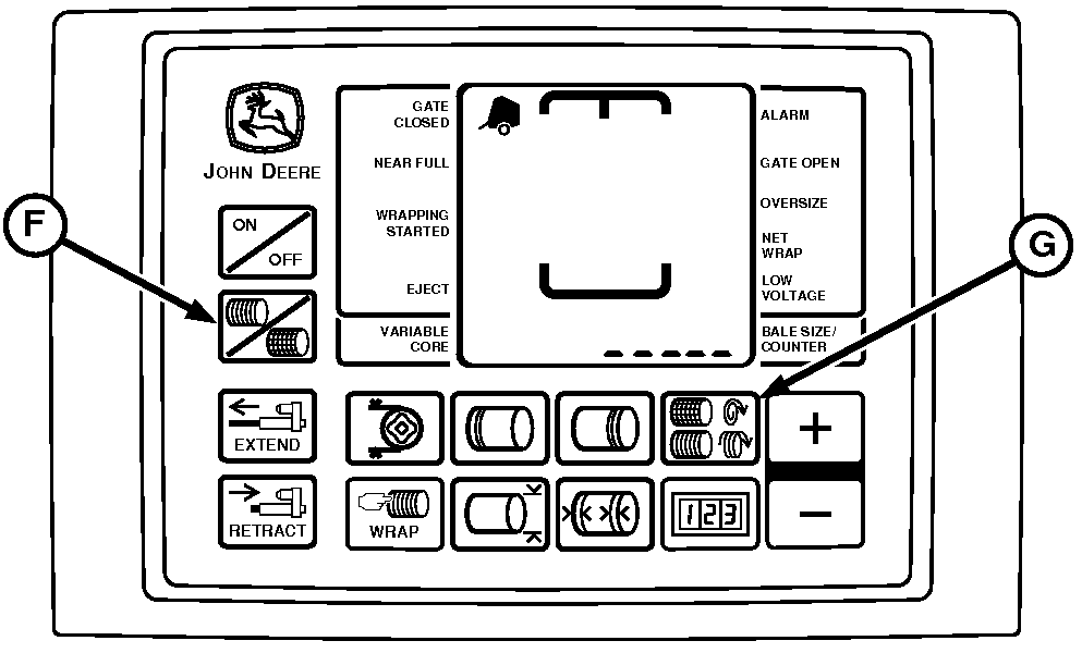
F - Twine Symbol
G - Twine Spacing Key
Set Mechanical Twine Arm Spacing:The monitor-controller maintains twine spacing for various bale diameters at rated PTO speed.
-
Set distance between the twine arms by installing spring pin (E) in the desired position:
Hole ID
Twine Arm Spacing
A
5 cm (2.0 in.)
B
10 cm (4.0 in.)
C
15 cm (6.0 in.)
D
20 cm (8.0 in.)
-
When operating at rated PTO speed, the monitor-controller twine spacing setting must be the same as the mechanical twine arm spacing.
-
If operating at less than rated PTO speed without the speed compensation sensors activated (See UNDERSTAND SLIP CLUTCH ALERT SYSTEM in this section)
Set Monitor-Controller Twine Spacing:
-
Turn tractor key to ON position. Do not start tractor engine. Turn monitor-controller to ON.
-
Press TWINE SPACING key (G). Press Plus or MINUS keys until desired twine spacing, 2—26 cm (1.0—10.0 in.) appears in digital display.
Use the following chart as a guideline. Monitor-controller settings can vary with crop conditions and between balers.
Engine rpm
Mechanical Setting
Monitor-Controller Setting
Rated Speed
10 cm (4.0 in.)
10 cm (4.0 in.)
1800 rpm
10 cm (4.0 in.)
9 cm (3.5 in.)
1500 rpm
10 cm (4.0 in.)
8 cm (3.0 in.)
1300 rpm
10 cm (4.0 in.)
6 cm (2.5 in.)
-
NOTE: Slip clutch alert, if turned on, applies desired number of twine wraps regardless of PTO speed.
Six seconds after last adjustment, setting will be entered into memory. Be sure monitor-controller twine spacing setting and mechanical twine arm spacing setting agree with each other.
-
Turn monitor-controller OFF. Turn tractor key to OFF position. Remove key.
|
PP98408,0001028-19-20130211 |