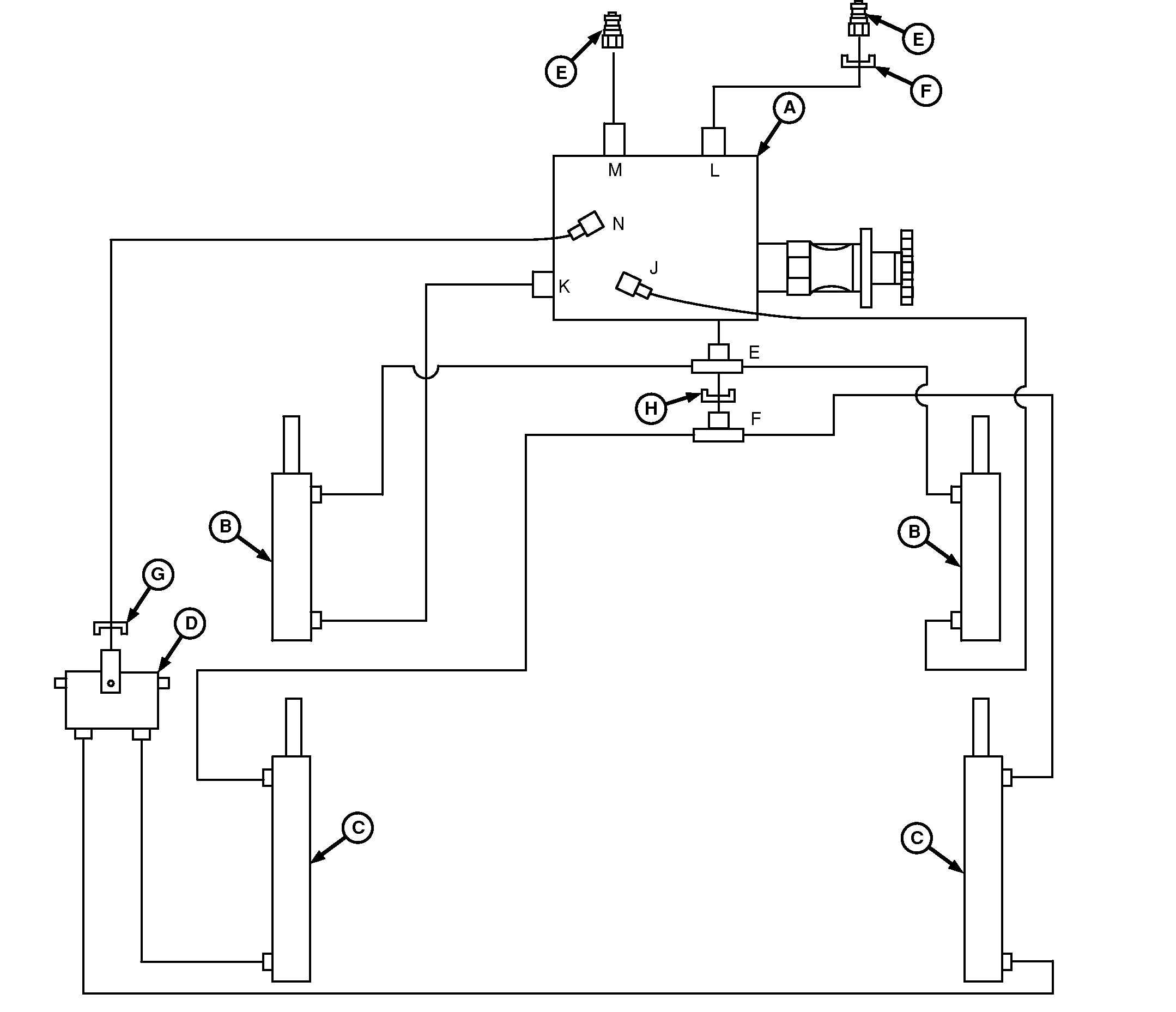
Hydraulic System Diagram
E67210-UN-15AUG12
A - Tensioning Valve
B - Tension Cylinders
C - Gate Cylinders
D - Gate Lock Valve
E - To Tractor SCV Ports
F - Orifice (Stamped 358)
G - Orifice (Stamped 365)
H - Orifice (Stamped 859)
John Deere 469, 469S, 569, and 569S Balers have a hydraulic system that controls bale tension and operates the gate. This hydraulic system is powered by the tractor.
The hydraulic system uses four major components:
- Tensioning valve (A)—Used to direct oil flow, check flow, and limit hydraulic pressures.
- Tensioning (double-acting) cylinders (B)—Used to control bale tensioning.
- Gate (double-acting) cylinders (C)—Used to raise and lower the gate.
- Gate lock valve (D)—A two-position spool valve used to block flow of oil, both to and from the base ports of gate cylinders (C).
|
PP98408,00010A0-19-20130211 |