Adjust PTO and Drive Roll (Pickup) Slip Clutch Alert Sensors
(MegaWide™ Plus and MegaTooth™ Pickups)
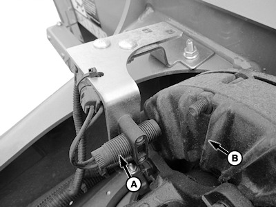
E69397-UN-11FEB13
PTO Sensor (540 rpm) Shown
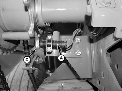
E69398-UN-08FEB13
Lower Drive Roll (Pickup) Sensor Shown
A - Sensor
B - PTO Clutch Fins
C - Tone Wheel
Clearance between sensor (A), PTO clutch fins (B), and tone wheel (C) must be with specification. A feeler gauge or washer of the correct thickness can be useful in adjusting setting.
| Item | Measurement | Specification |
| PTO Sensor | Clearance | 2 ± 1 mm (0.080 ± 0.040 in.) |
| Item | Measurement | Specification |
| Drive Roll Sensor | Clearance | 4 ± 1 mm (0.16 ± 0.040 in.) |
Verify Operation and Adjustment of Sensors
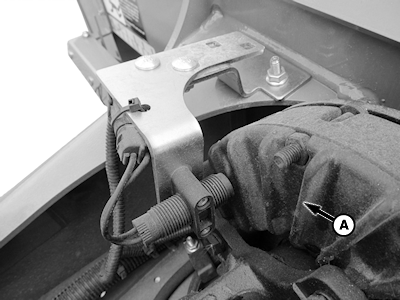
E69394-UN-11FEB13
PTO Sensor (540 rpm) Shown
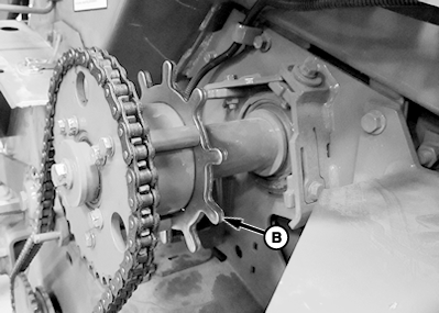
E69395-UN-08FEB13
Lower Drive Roll (Pickup) Sensor Shown
A - Clutch Fins
B - Tone Wheel
Use speed readout to verify operation and adjustment of sensors. Access channel 016 on monitor-controller for PTO speed and channel 017 for lower drive roll speed.-
Start tractor and operate tractor engine at slow idle. Engage PTO.
-
Press and hold COUNTER key while turning monitor-controller ON.
-
Continue to hold COUNTER key and press PLUS key until CH016 appears in digital display.
-
Release COUNTER key and PTO speed is displayed. Speed readout must be stable and not vary by ± 5 rpm.
-
Press and hold COUNTER key and press PLUS key until CH017 appears in digital display.
-
Release COUNTER key and pickup drive speed is displayed. Speed must be stable and not vary by ± 5 rpm.
-
If speed variation exceeds ± 5 rpm, shut off tractor and remove key.
Adjust PTO sensor closer to clutch fins (A) but not closer than 1 mm (0.04 in.). Adjust pickup sensor closer to tone wheel (B) nut not closer than 3 mm (0.12 in.).
When tractor is operated at rated PTO speed, channel 016 must display either 540 rpm or 1000 rpm. Channel 017 must display approximately 310 rpm. Slip clutch alert system must be activated within the monitor-controller for proper operation. (See TURN ON and OFF NET WRAP, SLIP CLUTCH ALERT, and VARIABLE CORE FEATURES in this section.)
Turning PTO Speed Sensor ON and OFF:
- PTO speed sensor can be turned OFF or ON by accessing channel 204.
- Feature can be turned ON by changing value to 540 or 1000 rpm.
- Entire slip clutch alert feature can be turned OFF by changing value to 0.
Turning Lower Drive Roll Speed Sensor ON and OFF:
- Pickup rpm sensor can be turned OFF and ON by accessing channel 205.
- Feature can be turned ON by changing value to 310 rpm.
- Pickup rpm sensor can be turned OFF by changing value to 0.
- Turning OFF the pickup sensor on channel 205 and turning ON PTO sensor on channel 204 still allows automatic speed compensation during wrapping cycle.
Adjusting PTO Sensor
-
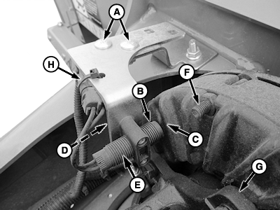
E69399-UN-11FEB13PTO Sensor (540 rpm) Shown
A - Round-Head Bolt and Flange Nut, M8 x 20 mm (2 used)
B - Sensor
C - Clutch Fins
D - Lock Nut (2 used)
E - End of Sensor
F - Clutch Screw
G - Clutch Yoke
H - Tie Band
Adjust end of sensor (B) 2 ± 1 mm (0.080 ± 0.040 in.) from clutch fins (C) on PTO clutch.NOTE: End of sensor is a magnet. Washer or feeler gauge can drag on magnet creating false sensor-to-fin reading during checks.
- Place a 2 mm (0.080 in.) washer or feeler gauge against end of sensor (B).
- Advance sensor (B with washer or feeler gauge toward clutch fins until gauge just makes contact.
-
To tighten sensor:
-
With clamp snug against bracket, tight bottom lock nut (D) an additional one full turn.
-
Tighten top lock nut (D) until slit closes completely, then tighten one additional full turn.
-
Gently pull on end of sensor (E) to verify it does not move.
-
Using a 35 mm (1-3/8 in.) wrench, go to left-hand side of baler and turn gearbox output shaft to verify end of sensor clears clutch screws (F) and clutch yoke (G).
-
Adjust sensor side-to-side by loosening and tightening nuts (A) as needed.
-
Remove wrench from output shaft on left-hand side of baler.
-
-
Verify that sensor is not damaged after tightening nuts.
- Connect multimeter leads to sensor connector.
- If multimeter reads approximately 3000 Ohms, sensor is good.
- If multimeter reads zero, sensor is bad. Replace sensor.
-
Recheck 2 ± 1 mm (0.080 ± 0.040 in.) clearance between clutch fins and sensor while gently prying PTO clutch forward to simulate PTO driveline thrust loads.
Hold PTO clutch forward and perform the following:
- If 1 mm (0.040 in.) gauge does not pass between clutch fin and sensor, repeat Steps 1—3 to obtain proper clearance.
- If 1 mm (0.040 in.) gauge passes between clutch fin and sensor, clearance is acceptable.
- If 3 mm (0.12 in.) gauge passes between clutch fin and sensor, repeat Steps 1—3 to obtain proper clearance.
-
Make sure that sensor bracket is equipped with a tie band (H). Tighten tie band around wiring harness connector and secure to bracket.
Adjusting Lower Drive (Pickup) Roll Sensor
-
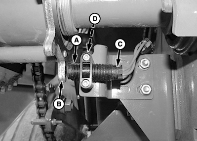
E69401-UN-08FEB13Lower Drive Roll Sensor
A - End of Sensor
B - Tone Wheel
C - Location, End of Sensor
D - Lock Nuts
Adjust end of sensor (A) 4 ± 1 mm (0.16 ± 0.04 in.) from tone wheel (B).NOTE: At end of sensor and each tone wheel tooth is a magnet. Washer or feeler gauge can drag on magnets creating false sensor-to-fin reading during rechecks.
- Using a 35 mm (1-3/8 in.) wrench, go to left-hand side of baler and turn gearbox output shaft until tone wheel tooth aligns with sensor.
- Remove wrench from gearbox output shaft on left-hand side of baler.
- Place two 2 mm (0.08 in.) washers or feeler gauge of this thickness against end of sensor (A).
- Advance sensor with washers or feeler gauge toward tone wheel until gauge just makes contact.
-
IMPORTANT: Overtightening clamp nuts can damage plastic block clamp.
To tighten sensor:
-
With clamp snug against bracket, tighten bottom lock nut (D) an additional one full turn.
-
Tighten top lock nut (D) until slit closes completely, then tighten one additional full turn.
-
Gently pull on end of sensor (C) to verify it does not move.
-
Remove washers or feeler gauge and recheck 4 ± 1 mm (0.16 ± 0.04 in.) dimension.
-
-
Verify that sensor is not damaged after tightening nuts.
- Connect multimeter leads to sensor connector.
- If multimeter reads approximately 3000 Ohms, sensor is good.
- If multimeter reads zero, sensor is bad. Replace sensor.
|
PP98408,00010BD-19-20130212 |