Sensor Input
W110
For diagnostic purposes each sensor input signal can be monitored. This helps in determining how each sensor is operating and if the proper output voltages are being received by the control system.
Select YES from the READ SENSOR INPUTS? screen to view the sensor voltages.
If NO is selected from the READ SENSOR INPUTS? screen the menu will move to ACTIVATE FUNCTIONS?.
If a sensor has been disabled, SENSOR will be flashing in the area where the input reading would have been.
E68811-UN-24OCT12
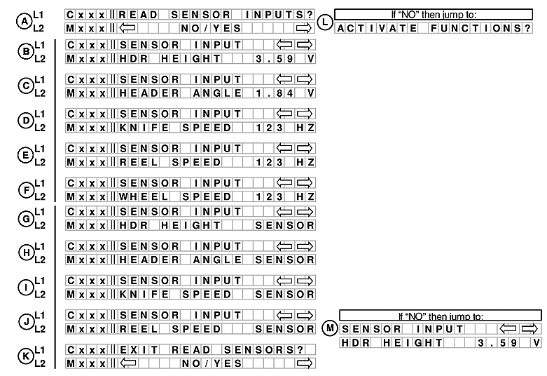
A. Line 1 - READ SENSOR INPUTS?. Line 2 displays NO/YES option.
If NO is selected from READ SENSOR INPUTS? menu moves to ACTIVATE FUNCTIONS?.
If NO is selected from READ SENSOR INPUTS? menu moves to ACTIVATE FUNCTIONS? (L).
B. Line 1 - SENSOR INPUT. Line 2 displays HDR HEIGHT and the voltage.
C. Line 1 - Sensor INPUT. Line 2 displays HEADER ANGLE and the voltage.
D. Line 1 - SENSOR INPUT. Line 2 displays KNIFE SPEED and the output.
E. Line 1 - SENSOR INPUT. Line 2 displays REEL SPEED and the output.
F. Line 1 - SENSOR INPUT. Line 2 displays WHEEL SPEED and the output. Adds a selection to read wheel speed frequency.
NOTE: If a sensor has been disabled SENSOR will be flashing in the area where the reading would have been.
G. Line 1 - SENSOR INPUT. Line 2 displays HDR HEIGHT SENSOR.
H. Line 1 - SENSOR INPUT. Line 2 displays HEADER ANGLE SENSOR.
I. Line 1 - SENSOR INPUT. Line 2 displays KNIFE SPEED SENSOR.
J. Line 1 - SENSOR INPUT. Line 2 displays REEL SPEED SENSOR.
K. Line 1 - EXIT READ SENSORS?. Line 2 displays NO/YES option.
If NO is selected from EXIT READ SENSORS? menu moves to SENSOR INPUT (M).
W150
E68812-UN-24OCT12
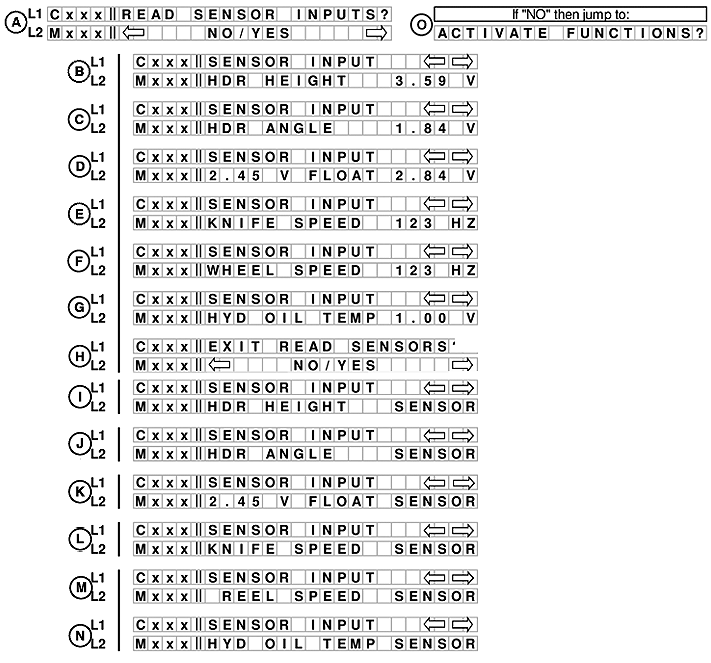
A. Line 1 - READ SENSOR INPUTS?. Line 2 displays NO/YES option.
If NO is selected from READ SENSOR INPUTS? menu moves to ACTIVATE FUNCTIONS? (L).
B. Line 1 - SENSOR INPUT. Line 2 displays HDR HEIGHT and voltage.
C. Line 1 - Sensor INPUT. Line 2 displays HEADER ANGLE and voltage.
D. Line 1 - SENSOR INPUT. Line 2 displays FLOAT and voltage.
E. Line 1 - SENSOR INPUT. Line 2 displays KNIFE SPEED and output.
F. Line 1 - SENSOR INPUT. Line 2 displays WHEEL SPEED and output. Adds a selection to read wheel speed frequency.
NOTE: If a sensor has been disabled SENSOR will be flashing in the area where the reading would have been.
G. Line 1 - SENSOR INPUT. Line 2 displays HYD OIL TEMP and voltage.
H. Line 1 - EXIT READ SENSORS?. Line 2 displays NO/YES option.
I. Line 1 - SENSOR INPUT. Line 2 displays HDR HEIGHT SENSOR.
J. Line 1 - SENSOR INPUT. Line 2 displays HDR ANGLE SENSOR.
K. Line 1 - SENSOR INPUT. Line 2 displays voltage FLOAT SENSOR.
L. Line 1 - SENSOR INPUT. Line 2 displays KNIFE SPEED SENSOR.
M. Line 1 - SENSOR INPUT. Line 2 displays REEL SPEED SENSOR.
N. Line 1 - SENSOR INPUT. Line 2 displays HYD OIL TEMP SENSOR.
|
RC48509,00006AB-19-20121030 |