Adjust Roller
-
It may be helpful to refer to exploded view. (See Plunger Rollers, Scrapers, and Track Exploded View in this section.)
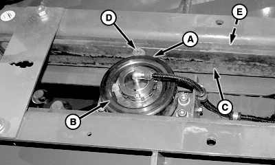
E77737-UN-18DEC14A - Distance
B - Roller (4 used)
C - Upper Rail (2 used)
D - Shims (as required)
Verify distance (A) between top of rollers (B) and upper rail (C) is within specification for entire length of plunger stroke.Top of Plunger Roller-to-Upper Track Distance 0.2—0.5 mm (0.008—0.02 in.) -
To adjust distance (A), loosen countersunk socket head cap screws to lower rail.
-
Add or remove shims (D) as required.
-
Tighten screws and recheck specification as described in Step 1.
|
SF04007,0000A1E-19-20160104 |